

Contents - Volkspage
Contents - Volkspage
Contents - Volkspage

Create successful ePaper yourself
Turn your PDF publications into a flip-book with our unique Google optimized e-Paper software.
10 000 mile/12 month service 1.7<br />
collect in the sump. Continue adding oil a<br />
small quantity at a time until the level is just<br />
above the lower mark on the dipstick. Adding<br />
approximately 1.0 litres will raise the level<br />
from the lower mark to the upper mark on the<br />
dipstick. Refit the filler cap.<br />
14 Start the engine and run it for a few<br />
minutes; check for leaks around the oil filter<br />
seal and the sump drain plug. Note that there<br />
may be a delay of a few seconds before the oil<br />
pressure warning light goes out when the<br />
engine is first started, as the oil circulates<br />
through the engine oil galleries and (where<br />
applicable) the new oil filter before the<br />
pressure builds up. If the oil pressure warning<br />
light does not extinguish after the engine has<br />
started and run for several seconds, stop the<br />
engine immediately and check for leaks<br />
around the components that have been<br />
disturbed.<br />
15 Switch off the engine, and wait a few<br />
minutes for the new oil to settle into the sump.<br />
With the new oil circulated and the filter now<br />
completely full, recheck the level on the<br />
dipstick, and add more oil as necessary.<br />
16 Dispose of the used engine oil safely, with<br />
reference to “General repair procedures” in<br />
the Reference Sections of this manual.<br />
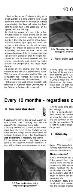
2.2a Checking the front brake outer pad<br />
linings for wear with a steel rule<br />
2 Front brake pad check<br />
1 Firmly apply the handbrake, then jack up<br />
the front of the car and support it securely on<br />
axle stands (see “Jacking and vehicle<br />
support”). Remove the front roadwheels.<br />
2 Using a steel rule, measure the combined<br />
thickness of the lining and backing of the<br />
brake pads on both front brakes. This must<br />
not be less than 7.0 mm. Check the inner pad<br />
2.2b Check the front brake inner pad<br />
linings through the hole in the caliper<br />
through the hole on the front of the caliper<br />
(see illustrations).<br />
3 For a comprehensive check, the brake pads<br />
should be removed and cleaned. The<br />
operation of the caliper can then also be<br />
checked, and the condition of the brake disc<br />
itself can be fully examined on both sides.<br />
Refer to Chapter 9 for further information.<br />
4 If any pad’s friction material is worn to the<br />
specified thickness or less, all four pads must.<br />
be renewed as a set. Refer to Chapter 9.<br />
5 On completion refit the roadwheels and<br />
lower the car to the ground.<br />
Every 12 months - regardless of mileage .<br />
1 Jack up the rear of the car and support on<br />
axle stands (see “Jacking and vehicle<br />
support”). Do not remove the wheels.<br />
2 Working beneath the car remove the rubber<br />
plugs from the front of the backplates and<br />
check that the linings are not worn below the<br />
minimum thickness given in the Specifications<br />
(see illustration). If necessary use a torch.<br />
3 If the friction material on any shoe is worn<br />
down to the specified minimum thickness or<br />
less, all four shoes must be renewed as a set.<br />
3.2 Rear brake shoe lining<br />
inspection plug location<br />
4 At the same time check for signs of brake<br />
fluid leakage.<br />
5 For a comprehensive check, the brake<br />
drum should be removed and cleaned. This<br />
will allow the wheel cylinders to be checked,<br />
and the condition of the brake drum itself to<br />
be fully examined (see Chapter 9).<br />
6 Refit the rubber plugs then lower the car to<br />
the ground.<br />
Note: This procedure does not apply to<br />
vehicles fitted with an automatic clutch cab/e<br />
adjustment mechanism.<br />
Measurement<br />
1 Park the vehicle and switch off the engine.<br />
Select neutral, then depress the clutch pedal<br />
several times, to settle the release mechanism<br />
components. With no pressure applied to the<br />
pedal, measure the distance between the<br />
pedal rubber and a fixed reference point, such<br />
as the bottom edge of the steering wheel - a<br />
length of batten can be used to serve as a<br />
measuring rule.<br />
2 Gradually apply pressure to the clutch<br />
pedal, until firm resistance is felt, indicating<br />
that the release mechanism is beginning to<br />
disengage the clutch. At this point, repeat the<br />
measurement described in paragraph 1.<br />
3 Compare the measurement with the value<br />
listed in the Specifications - if the free play<br />
exceeds the maximum permitted, adjust the<br />
cable as described in the following sub- :<br />
Section.<br />
Adjustment<br />
4 Open the bonnet and locate the clutch<br />
cable adjusting nut, on the upper surface of<br />
the transmission casing.<br />
5 Rotate the nut through half a turn, using a<br />
spanner, to take up the slack in the cable.<br />
Measure the clutch pedal freeplay again, as<br />
described in the previous sub-Section.<br />
6 Repeat the operations described in<br />
paragraphs 4 and 5 until the correct pedal<br />
freeplay is achieved.<br />
5<br />
1 Visually inspect the engine joint faces,<br />
gaskets and seals for any signs of water or oil<br />
leaks. Pay particular attention to the areas<br />
around the camshaft cover, cylinder head, oil<br />
filter and sump joint faces. Bear in mind that,<br />
over a period of time, some very slight<br />
seepage from these areas is to be expected -


