

Contents - Volkspage
Contents - Volkspage
Contents - Volkspage

Create successful ePaper yourself
Turn your PDF publications into a flip-book with our unique Google optimized e-Paper software.
4C.2 Emission control and exhaust systems<br />
Exhaust systems<br />
9 The exhaust system comprises the exhaust<br />
manifold, a number of silencer units (depending<br />
on model and specification), a catalytic<br />
converter (where fitted), a number of mounting<br />
brackets and a series of connecting pipes.<br />
General information<br />
1 The evaporative loss emission control<br />
system consists of the purge valve, the<br />
activated charcoal filter canister and a series<br />
of connecting vacuum hoses.<br />
2 The purge valve is mounted on a bracket<br />
behind the air cleaner housing, and the<br />
charcoal canister is mounted on a bracket<br />
above the right hand front wheel housing.<br />
Purge valve<br />
3 On single-point injection models, ensure<br />
that the ignition is switched off, then unplug<br />
the wiring harness from the purge valve at the<br />
connector.<br />
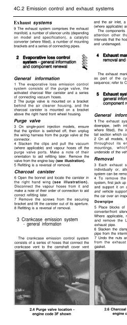
4 Slacken the clips and pull the vacuum<br />
(where applicable) and vapour hoses off the<br />
purge valve ports. Make a note of their<br />
orientation to aid refitting later. Remove the<br />
valve from the engine bay (see illustration).<br />
5 Refitting is a reversal of removal.<br />
Charcoal canister<br />
6 Open the bonnet and locate the canister in<br />
the right hand wing (see illustration).<br />
Disconnect the vapour hoses from it and<br />
make a note of their order of connection to aid<br />
correct refitting later.<br />
7 Remove the screws from the securing<br />
bracket and lift the canister out of its aperture.<br />
8 Refitting is a reversal of removal.<br />
3 Crankcase emission system<br />
- general information<br />
The crankcase emission control system<br />
consists of a series of hoses that connect the<br />
crankcase vent to the camshaft cover vent<br />
and the air inlet, a pressure regulating valve<br />
(where applicable) and an oil separator unit.<br />
The components of this system require no<br />
attention other than to check at regular<br />
intervals that the hose(s) are free of blockages<br />
and undamaged.<br />
The exhaust manifold removal is described<br />
as part of the cylinder head dismantling<br />
sequence; refer to Chapter 2A.<br />
General information<br />
1 The exhaust system is made up of the<br />
downpipe, (with integral catalytic converter,<br />
where fitted), the intermediate pipe and the<br />
tail section which contains the rear silencer.<br />
2 On all models, the system is suspended<br />
throughout its entire length by rubber<br />
mountings, which are secured to the<br />
underside of the vehicle by metal brackets.<br />
Removal<br />
3 Each exhaust section can be removed<br />
individually or, alternatively, the complete<br />
system can be removed as a unit.<br />
4 To remove the system or part of the<br />
system, first jack up the front or rear of the car<br />
and support it on axle stands (see “Jacking<br />
and vehicle support”). Alternatively position<br />
the car over an inspection pit or on car ramps.<br />
Downpipe<br />
5 Place blocks of wood under the catalytic<br />
converter/front silencer to act as a support.<br />
Where applicable, refer to Chapter 4A or B<br />
and remove the Lambda sensor from the<br />
exhaust pipe.<br />
6 Slacken the clamp and separate the down<br />
pipe from the intermediate pipe.<br />
7 Undo the nuts and separate the downpipe<br />
from the exhaust manifold. Recover the<br />
gasket.<br />
2.4 Purge valve location - 2.6 Charcoal canister location -<br />
engine code 3F shown<br />
engine code 3F shown<br />
Catalytic converter<br />
8 Where fitted, the catalytic converter is<br />
integral with the down pipe.<br />
Intermediate pipe<br />
9 Slacken the clamping ring bolts and<br />
disengage the clamp from the intermediate<br />
pipe-to-tailpipe joint and the intermediate<br />
pipe-to-catalytic converter/front silencer joint.<br />
10 Disengage the intermediate pipe from the<br />
tailpipe and the catalytic converter/front<br />
silencer and remove it from underneath the<br />
vehicle.<br />
Tailpipe<br />
11 Slacken the clamping ring bolts and<br />
disengage the tailpipe at the joint.<br />
12 Unhook the tailpipe from its mounting<br />
rubbers and remove it from the vehicle.<br />
Complete system<br />
13 Disconnect the down pipe from the<br />
manifold as described earlier in this Section.<br />
14 With the aid of an assistant, free the<br />
system from all its mounting rubbers and<br />
manoeuvre it out from underneath the vehicle.<br />
Heatshields<br />
15 The heatshields, where fitted, are secured<br />
to the underside of the body by a combination<br />
of nuts, bolts and clips. Each shield can be<br />
removed once the relevant exhaust section<br />
has been removed. Note that if the shield is<br />
being removed to gain access to a<br />
component located behind it, in some cases it<br />
may prove sufficient to remove the retaining<br />
nuts and/or bolts and simply lower the shield,<br />
removing the need to disturb the exhaust<br />
system.<br />
Refitting<br />
16 Each section is refitted by a reverse of the<br />
removal sequence, noting the following<br />
points.<br />
a) Ensure that all traces of corrosion have<br />
been removed from the flanges and<br />
renew all necessary gaskets.<br />
b) inspect the rubber mountings for signs of<br />
damage or deterioration and renew as<br />
necessary.<br />
c) On joints which are secured by clamping<br />
rings, apply a smear of exhaust system<br />
jointing paste to the joint mating surfaces<br />
to ensure an air-tight seal. Tighten the<br />
clamping ring nuts evenly and<br />
progressively to the specified torque so<br />
that the clearance between the clamp<br />
halves is equal on either side.<br />
d) Prior to tightening the exhaust system<br />
fastenets, ensure that all rubber<br />
mountings are correctly located and that<br />
there is adequate clearance between the<br />
exhaust system and vehicle underbody.


