

Contents - Volkspage
Contents - Volkspage
Contents - Volkspage

You also want an ePaper? Increase the reach of your titles
YUMPU automatically turns print PDFs into web optimized ePapers that Google loves.
10.4 Suspension and steering<br />
Note: VW tool 40-201 B is necessary in order<br />
to unscrew the screw cap from the top of the<br />
strut.<br />
1 A faulty shock absorber will normally make<br />
a knocking noise as the car is driven over<br />
rough surfaces.<br />
2 To remove the shock absorber first remove<br />
the front coil spring as described in Section 3.<br />
3 Using VW tool 40-201 B unscrew the screw<br />
cap from the top of the strut and remove the<br />
piston rod guide and seal. If necessary first<br />
mount the strut in a vice.<br />
4 Pull the shock absorber out of the strut then<br />
pour the remaining fluid out and discard it.<br />
Clean the inside of the strut with paraffin and<br />
wipe dry.<br />
5 Replacement shock absorbers are supplied<br />
as dry type cartridges, the wet type are only<br />
fitted by the factory when new.<br />
6 With the new shock absorber upright,<br />
operate it fully several times and check that<br />
the resistance is even without any tight spots.<br />
7 Insert the shock absorber in the strut and fit<br />
the guide together with a new seal.<br />
8 Fit the screw cap and tighten it to the<br />
specified torque.<br />
9 Refit the coil spring as described in Section<br />
3.<br />
Testing<br />
1 Jack up the front of the car and support on<br />
axle stands (see “Jacking and vehicle<br />
support”). With neutral selected, spin the<br />
wheel. A rumbling noise will be evident if the<br />
bearings are worn and excessive play will be<br />
apparent when the wheel is rocked, however<br />
check that the lower balljoint is not<br />
responsible for the play.<br />
Renewal<br />
2 To renew the wheel bearings first remove<br />
the suspension strut as described in Section<br />
2.<br />
3 Support the outside of the strut, then using<br />
a suitable metal tube, drive the hub from the<br />
wheel bearing. The outer bearing race will be<br />
forced from the bearing during this procedure<br />
and therefore it is not possible to re-use the<br />
bearing.<br />
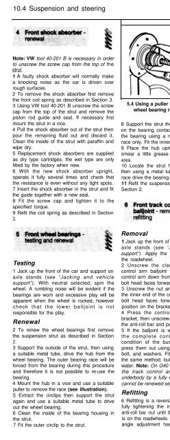
4 Mount the hub in a vice and use a suitable<br />
puller to remove the race (see illustration).<br />
5 Extract the circlips then support the strut<br />
again and use a suitable metal tube to drive<br />
out the wheel bearing.<br />
6 Clean the inside of the bearing housing in<br />
the strut.<br />
7 Fit the outer circlip to the strut.<br />
5.4 Using a puller to remove the outer<br />
wheel bearing race from the hub<br />
8 Support the strut then smear a little grease<br />
on the bearing contact surfaces and drive in<br />
the bearing using a metal tube on the outer<br />
race only. Fit the inner circlip.<br />
9 Place the hub upright on the bench and<br />
smear a little grease on the bearing contact<br />
area.<br />
10 Locate the strut horizontally on the hub,<br />
then using a metal tube on the bearing inner<br />
race drive the bearing fully onto the hub.<br />
11 Refit the suspension strut as described in<br />
Section 2.<br />
Removal<br />
1 Jack up the front of the car and support on<br />
axle stands (see “Jacking and vehicle<br />
support”). Apply the handbrake and remove<br />
the roadwheel.<br />
2 Unscrew the clamp bolt securing the<br />
control arm balljoint to the strut. Press the<br />
control arm down from the strut. Note that the<br />
bolt head faces forward.<br />
3 Unscrew the nut and remove the bolt from<br />
the inner end of the control arm. Note that the<br />
bolt head faces forward, and also mark its<br />
position on the bracket.<br />
4 Press the control arm down from the<br />
bracket, then unscrew the nut from the end of<br />
the anti-roll bar and pull off the control arm.<br />
5 If the balljoint is worn excessively, renew<br />
the complete control arm. Check the<br />
condition of the bushes and if necessary<br />
press them out using a metal tube, nut and<br />
bolt, and washers. Fit the new bushes using<br />
the same method, but first dip them in soapy<br />
water. Note: On G40 models the inner end of<br />
the track control arm is attached to the<br />
underbody by a fully enclosed ball joint which<br />
cannot be renewed separately.<br />
Refitting<br />
6 Refitting is a reversal of removal, but delay<br />
fully tightening the inner pivot bolt and the<br />
anti-roll bar nut until the full weight of the car<br />
is on the roadwheels. Note that where camber<br />
angle adjustment has been made, the bolt<br />
Removal<br />
1 Jack up the front of the car and support<br />
with axle stands (see “Jacking and vehicle<br />
support”). Remove both wheels and apply the<br />
handbrake.<br />
2 Note that with the anti-roll bar correctly<br />
fitted, the bend in the front of the bar faces<br />
upwards.<br />
3 Unscrew the bolts and remove the<br />
mounting clamps securing the front of the bar<br />
to the underbody bracket (see illustration).<br />
4 Unscrew and remove the nuts and washers<br />
from the ends of the anti-roll bar.<br />
5 Pull the anti-roll bar from the control arms<br />
and withdraw it from under the car. If difficulty<br />
is experienced, temporarily jack up the control<br />
arms to give a little extra width for the removal<br />
of the bar.<br />
6 Check the bar and rubber bushes for wear<br />
and deterioration and renew as necessary. If<br />
the bush in the control arm is worn, renew it<br />
with reference to Section 6. Note: The bushes<br />
fitted to the G40 model are harder than those<br />
fitted to other models.<br />
Refitting<br />
7.3 Top view of the anti-roll bar<br />
front mounting bracket<br />
(engine removed from car)<br />
hole in the bracket may have been elongated<br />
and in this case it is imperative that the<br />
special bush and bolt are refitted in their<br />
original position otherwise the adjustment will<br />
have to be repeated.<br />
7 Refitting is a reversal of removal, but delay<br />
fully tightening the nuts and bolts until the full<br />
weight of the car is on the roadwheels. The<br />
bend in the front section of the bar must face<br />
upwards. Note that the castor angle is<br />
determined by the position of the control arms<br />
on the anti-roll bar, therefore any adjustment<br />
washers should be refitted in their original<br />
locations.


