

Contents - Volkspage
Contents - Volkspage
Contents - Volkspage

Create successful ePaper yourself
Turn your PDF publications into a flip-book with our unique Google optimized e-Paper software.
5B.4 Ignition systems<br />
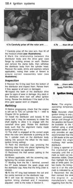
4.7a Carefully prise off the rotor arm . . .<br />
7 Carefully prise off the rotor arm, then lift off<br />
the moisture shield (see illustrations).<br />
8 Mark the relationship between the<br />
distributor body and the drive gear case<br />
flange by scribing arrows on each. Slacken<br />
and remove the clamp bolts, then withdraw<br />
the distributor body from the cylinder head.<br />
Recover the seals, shims and washers (where<br />
applicable), noting their order of fitment to<br />
ensure correct reassembly later (see<br />
illustrations).<br />
Inspection<br />
9 Recover the O-ring seal from the bottom of<br />
the distributor and inspect them. Renew them<br />
if they appear at all worn or damaged.<br />
10 Inspect the teeth of the distributor drive<br />
gear for signs of wear or damage. Any slack in<br />
the distributor drive train will affect ignition<br />
timing. Renew the distributor if the teeth of the<br />
drive gear appear worn or chipped.<br />
Refitting<br />
11 Before progressing, check that the engine<br />
is still set to TDC on cylinder No 1 - refer to<br />
Chapter 2A for guidance.<br />
12 Install the distributor and loosely fit the<br />
clamp bolt; it may be necessary to rotate the<br />
shaft slightly to allow it to engage with the<br />
camshaft drive gear. Rotate the distributor<br />
body such that the alignment marks made<br />
during removal line up.<br />
13 The shaft is engaged at the correct angle<br />
when the rotor arm electrode is pointing at the<br />
No 1 cylinder mark on the distributor body<br />
(taking into account the offset for the basic<br />
ignition timing setting).<br />
14 Refit the distributor cap, pressing the<br />
retaining clips firmly into place/ tightening the<br />
retaining screws (as applicable).<br />
15 Reconnect the Hall sensor cabling to the<br />
distributor.<br />
16 Where applicable, refit the screening cap,<br />
tightening the screws securely.<br />
17 Working from the No 1 terminal, connect<br />
the HT leads between the spark plugs and<br />
the distributor cap. Note that the firing order is<br />
l-3-4-2.<br />
18 Fit the HT king lead between the coil and<br />
the centre terminal on the distributor cap.<br />
19 It will now be necessary to have the<br />
ignition timing checked and if necessary<br />
adjusted - refer to the notes in Section 5.<br />
4.7b . . . then lift off the moisture shield 4.8a Slacken and remove<br />
the clamp bolts . . .<br />
4.8b . . .then withdraw the distributor<br />
body from the cylinder head . . .<br />
Note: The engine should be at normal<br />
operating temperature to ensure correct<br />
results<br />
Note: Accurate checking and setting of the<br />
ignition timing is only possible using a special<br />
instrument connected to the flywheel TDC<br />
sender unit through the aperture in the top of<br />
the gearbox be//housing. This will not normally<br />
be available to the home mechanic, so a<br />
method using a stroboscopic timing light is<br />
described below. It should be noted that this<br />
only provides an approximate setting - it is<br />
recommended that the vehicle be checked by<br />
a VW dealer at the earliest opportunity.<br />
1 Disable the engine by unplugging the<br />
multiway Hall sender connector from the<br />
distributor.<br />
2 Using a spanner or socket and wrench on<br />
the crankshaft pulley, turn the engine<br />
manually until the crankshaft pulley timing<br />
mark (a notch cut into the edge of the pulley)<br />
becomes visible. Clean the edge of the pulley,<br />
then highlight the timing mark with chalk or a<br />
dab of white paint. On G40 models, there are<br />
two marks: the timing mark has a ‘Z’ stamped<br />
next to it on the crankshaft pulley (the TDC<br />
mark is indicated by an ‘0’).<br />
3 Reconnect the distributor multiway plug,<br />
then connect the stroboscopic timing light to<br />
the engine in accordance with the<br />
manufacturer’s instructions, so that it is<br />
triggering from the No 1 cylinder HT lead.<br />
4.8c Recover the seals<br />
4 Start the engine and run it at idling speed.<br />
Direct the beam from the timing light at the<br />
pointer protruding from the timing belt cover.<br />
The stroboscopic effect should ‘freeze’ the<br />
motion of the crankshaft pulley and the<br />
highlighted timing mark. If the mark appears<br />
to be moving back and forth, this may be due<br />
erratic idling - check that all of the cars<br />
electrical accessories are switched off and<br />
that the auxiliary cooling fan is not running.<br />
The engine should be at normal operating<br />
temperature, but the idle speed may be<br />
become unstable if it is particularly hot day<br />
and the engine has been idling for some time.<br />
5 The highlighted timing mark should appear<br />
to be stationary and aligned with the pointer<br />
on the timing belt cover (see illustrations). If<br />
they are not aligned, the basic ignition setting<br />
requires adjustment.<br />
6 To adjust the basic ignition timing setting,<br />
first switch off the engine, to avoid the risk of<br />
a getting a shock from the HT voltage. Refer<br />
5.5a Ignition timing marks -<br />
all models except G40


