

Contents - Volkspage
Contents - Volkspage
Contents - Volkspage

Create successful ePaper yourself
Turn your PDF publications into a flip-book with our unique Google optimized e-Paper software.
3.4 Cooling, heating and ventilation systems<br />
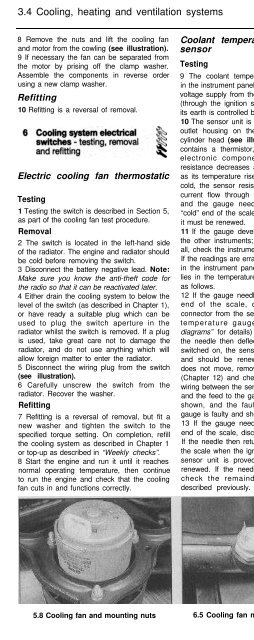
8 Remove the nuts and lift the cooling fan<br />
and motor from the cowling (see illustration).<br />
9 If necessary the fan can be separated from<br />
the motor by prising off the clamp washer.<br />
Assemble the components in reverse order<br />
using a new clamp washer.<br />
Refitting<br />
10 Refitting is a reversal of removal.<br />
Electric cooling fan thermostatic<br />
Testing<br />
1 Testing the switch is described in Section 5,<br />
as part of the cooling fan test procedure.<br />
Removal<br />
2 The switch is located in the left-hand side<br />
of the radiator. The engine and radiator should<br />
be cold before removing the switch.<br />
3 Disconnect the battery negative lead. Note:<br />
Make sure you know the anti-theft code for<br />
the radio so that it can be reactivated later.<br />
4 Either drain the cooling system to below the<br />
level of the switch (as described in Chapter 1),<br />
or have ready a suitable plug which can be<br />
used to plug the switch aperture in the<br />
radiator whilst the switch is removed. If a plug<br />
is used, take great care not to damage the<br />
radiator, and do not use anything which will<br />
allow foreign matter to enter the radiator.<br />
5 Disconnect the wiring plug from the switch<br />
(see illustration).<br />
6 Carefully unscrew the switch from the<br />
radiator. Recover the washer.<br />
Refitting<br />
7 Refitting is a reversal of removal, but fit a<br />
new washer and tighten the switch to the<br />
specified torque setting. On completion, refill<br />
the cooling system as described in Chapter 1<br />
or top-up as described in “Weekly checks”.<br />
8 Start the engine and run it until it reaches<br />
normal operating temperature, then continue<br />
to run the engine and check that the cooling<br />
fan cuts in and functions correctly.<br />
Coolant temperature gauge<br />
sensor<br />
Testing<br />
9 The coolant temperature gauge, mounted<br />
in the instrument panel, is fed with a stabilised<br />
voltage supply from the instrument panel feed<br />
(through the ignition switch and a fuse), and<br />
its earth is controlled by the sensor.<br />
10 The sensor unit is clipped into the coolant<br />
outlet housing on the left-hand end of the<br />
cylinder head (see illustration). The sensor<br />
contains a thermistor, which consists of an<br />
electronic component whose electrical<br />
resistance decreases at a predetermined rate<br />
as its temperature rises. When the coolant is<br />
cold, the sensor resistance is high, therefore<br />
current flow through the gauge is reduced,<br />
and the gauge needle points towards the<br />
“cold” end of the scale. If the sensor is faulty,<br />
it must be renewed.<br />
11 If the gauge develops a fault, first check<br />
the other instruments; if they do not work at<br />
all, check the instrument panel electrical feed.<br />
If the readings are erratic, there may be a fault<br />
in the instrument panel assembly. If the fault<br />
lies in the temperature gauge alone, check it<br />
as follows.<br />
12 If the gauge needle remains at the “cold”<br />
end of the scale, disconnect the wiring<br />
connector from the sensor unit, and earth the<br />
temperature gauge wire (see “Wiring<br />
diagrams” for details) to the cylinder head. If<br />
the needle then deflects when the ignition is<br />
switched on, the sensor unit is proved faulty,<br />
and should be renewed. If the needle still<br />
does not move, remove the instrument panel<br />
(Chapter 12) and check the continuity of the<br />
wiring between the sensor unit and the gauge,<br />
and the feed to the gauge unit. If continuity is<br />
shown, and the fault still exists, then the<br />
gauge is faulty and should be renewed.<br />
13 If the gauge needle remains at the “hot”<br />
end of the scale, disconnect the sensor wire.<br />
If the needle then returns to the “cold” end of<br />
the scale when the ignition is switched on, the<br />
sensor unit is proved faulty and should be<br />
renewed. If the needle still does not move,<br />
check the remainder of the circuit as<br />
described previously.<br />
Removal<br />
14 Either partially drain the cooling system to<br />
just below the level of the sensor (as<br />
described in Chapter 1), or have ready a<br />
suitable plug which can be used to plug the<br />
sensor aperture whilst it is removed. If a plug<br />
is used, take great care not to damage the<br />
sensor unit aperture, and do not use anything<br />
which will allow foreign matter to enter the<br />
cooling system.<br />
15 Disconnect the wiring from the sensor.<br />
16 Depress the sensor unit and slide out its<br />
retaining clip. Withdraw the sensor from the<br />
coolant elbow and recover its sealing ring.<br />
Refitting<br />
17 Fit a new sealing ring to the sensor unit.<br />
Push the sensor fully into the coolant elbow<br />
and secure it in position with the retaining clip.<br />
18 Reconnect the wiring connector then refill<br />
the cooling system as described in Chapter 1<br />
or top-up as described in “Weekly checks”.<br />
Removal<br />
1 Drain the cooling system (see Chapter 1).<br />
2 Where necessary, remove the air cleaner<br />
and air ducting as described in Chapter 4, and<br />
disconnect the battery negative lead.<br />
3 Unbolt and remove the timing belt cover.<br />
4 Turn the engine with a spanner on the<br />
crankshaft pulley bolt until the timing belt<br />
inner cover retaining bolt is visible through the<br />
camshaft sprocket hole. Unscrew and remove<br />
the bolt.<br />
5 Align the timing marks and release the<br />
timing belt from the water pump and camshaft<br />
sprocket with reference to Chapter 2. Also<br />
unbolt and remove the camshaft sprocket.<br />
6 Remove the bolts and withdraw the timing<br />
belt inner cover followed by the water pump.<br />
Remove the sealing ring (see illustrations).<br />
Inspection<br />
7 It is not possible to repair the water pump; if<br />
faulty it must be renewed. Clean the mating<br />
faces of the water pump and cylinder block.<br />
5.8 Cooling fan and mounting nuts 6.5 Cooling fan motor thermoswitch 6.10 Coolant temperature gauge sensor<br />
clipped into the coolant outlet housing on<br />
the left-hand end of the cylinder head


