

Contents - Volkspage
Contents - Volkspage
Contents - Volkspage

Create successful ePaper yourself
Turn your PDF publications into a flip-book with our unique Google optimized e-Paper software.
Engine removal and overhaul procedures 2B.7<br />
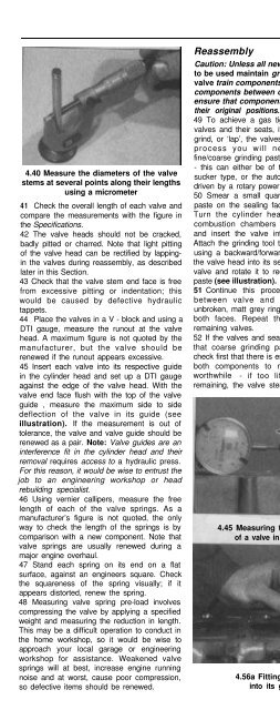
4.40 Measure the diameters of the valve<br />
stems at several points along their lengths<br />
using a micrometer<br />
41 Check the overall length of each valve and<br />
compare the measurements with the figure in<br />
the Specifications.<br />
42 The valve heads should not be cracked,<br />
badly pitted or charred. Note that light pitting<br />
of the valve head can be rectified by lappingin<br />
the valves during reassembly, as described<br />
later in this Section.<br />
43 Check that the valve stem end face is free<br />
from excessive pitting or indentation; this<br />
would be caused by defective hydraulic<br />
tappets.<br />
44 Place the valves in a V - block and using a<br />
DTI gauge, measure the runout at the valve<br />
head. A maximum figure is not quoted by the<br />
manufacturer, but the valve should be<br />
renewed if the runout appears excessive.<br />
45 Insert each valve into its respective guide<br />
in the cylinder head and set up a DTI gauge<br />
against the edge of the valve head. With the<br />
valve end face flush with the top of the valve<br />
guide , measure the maximum side to side<br />
deflection of the valve in its guide (see<br />
illustration). If the measurement is out of<br />
tolerance, the valve and valve guide should be<br />
renewed as a pair. Note: Valve guides are an<br />
interference fit in the cylinder head and their<br />
removal requires access to a hydraulic press.<br />
For this reason, it would be wise to entrust the<br />
job to an engineering workshop or head<br />
rebuilding specialist.<br />
46 Using vernier callipers, measure the free<br />
length of each of the valve springs. As a<br />
manufacturer’s figure is not quoted, the only<br />
way to check the length of the springs is by<br />
comparison with a new component. Note that<br />
valve springs are usually renewed during a<br />
major engine overhaul.<br />
47 Stand each spring on its end on a flat<br />
surface, against an engineers square. Check<br />
the squareness of the spring visually; if it<br />
appears distorted, renew the spring.<br />
48 Measuring valve spring pre-load involves<br />
compressing the valve by applying a specified<br />
weight and measuring the reduction in length.<br />
This may be a difficult operation to conduct in<br />
the home workshop, so it would be wise to<br />
approach your local garage or engineering<br />
workshop for assistance. Weakened valve<br />
springs will at best, increase engine running<br />
noise and at worst, cause poor compression,<br />
so defective items should be renewed.<br />
Reassembly<br />
Caution: Unless all new components are<br />
to be used maintain groups when refitting<br />
valve train components - do not mix<br />
components between cylinders and<br />
ensure that components are refitted in<br />
their original positions.<br />
49 To achieve a gas tight seal between the<br />
valves and their seats, it will be necessary to<br />
grind, or ‘lap’, the valves in. To complete this<br />
process you will need a quantity of<br />
fine/coarse grinding paste and a grinding tool<br />
- this can either be of the dowel and rubber<br />
sucker type, or the automatic type which are<br />
driven by a rotary power tool.<br />
50 Smear a small quantity of fine grinding<br />
paste on the sealing face of the valve head.<br />
Turn the cylinder head over so that the<br />
combustion chambers are facing upwards<br />
and insert the valve into the correct guide.<br />
Attach the grinding tool to the valve head and<br />
using a backward/forward rotary action, grind<br />
the valve head into its seat. Periodically lift the<br />
valve and rotate it to redistribute the grinding<br />
paste (see illustration).<br />
51 Continue this process until the contact<br />
between valve and seat produces an<br />
unbroken, matt grey ring of uniform width, on<br />
both faces. Repeat the operation for the<br />
remaining valves.<br />
52 If the valves and seats are so badly pitted<br />
that coarse grinding paste must be used,<br />
check first that there is enough material left on<br />
both components to make this operation<br />
worthwhile - if too little material is left<br />
remaining, the valve stems may protrude too<br />
4.45 Measuring the deflection<br />
of a valve in its guide<br />
4.56a Fitting a valve<br />
into its guide<br />
far above their guides, impeding the correct<br />
operation of the hydraulic tappets. Refer to a<br />
machine shop or cylinder head rebuilding<br />
specialist for advice.<br />
53 Assuming the repair is feasible, work as<br />
described in the previous paragraph but use<br />
the coarse grinding paste initially, to achieve a<br />
dull finish on the valve face and seat. Then,<br />
wash off coarse paste with solvent and repeat<br />
the process using fine grinding paste to obtain<br />
the correct finish.<br />
54 When all the valves have been ground in,<br />
remove all traces of grinding paste from the<br />
cylinder head and valves with solvent and<br />
allow them to dry completely.<br />
55 Turn the head over and place it on a<br />
stand, or wooden blocks. Leave enough<br />
room underneath to allow the valves to be<br />
inserted.<br />
56 Working on one valve at a time, lubricate<br />
the valve stem with clean engine oil and insert<br />
it into the guide. Fit one of the protective<br />
plastic sleeves supplied with the new valve<br />
stem oil seals over the valve end face - this<br />
will protect the oil seal whilst it is being fitted<br />
(see illustrations).<br />
57 Dip a new valve stem seal in clean engine<br />
oil and carefully push it over the valve and<br />
onto the top of the valve guide - take care not<br />
to damage the stem seal as it passes over the<br />
valve end face. Use a suitable long reach<br />
socket to press it firmly into position (see<br />
illustration).<br />
58 Locate the valve spring(s) over the valve<br />
stem. Where a lower spring seat is fitted,<br />
ensure that the springs locate squarely on the<br />
4.50 Grinding in a valve<br />
4.56b Fitting a protective plastic sleeve<br />
over the valve end face


