

Contents - Volkspage
Contents - Volkspage
Contents - Volkspage

Create successful ePaper yourself
Turn your PDF publications into a flip-book with our unique Google optimized e-Paper software.
Every 12 months - regardless of mileage 1.9<br />
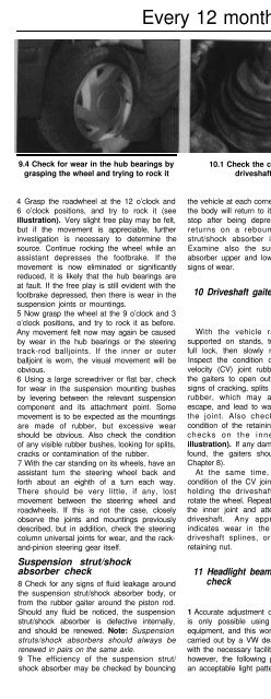
9.4 Check for wear in the hub bearings by<br />
grasping the wheel and trying to rock it<br />
10.1 Check the condition of the<br />
driveshaft gaiters<br />
11.4 Headlight beam adjustment screws<br />
A Vertical adjustment<br />
B Horizontal adjustment<br />
4 Grasp the roadwheel at the 12 o’clock and<br />
6 o’clock positions, and try to rock it (see<br />
illustration). Very slight free play may be felt,<br />
but if the movement is appreciable, further<br />
investigation is necessary to determine the<br />
source. Continue rocking the wheel while an<br />
assistant depresses the footbrake. If the<br />
movement is now eliminated or significantly<br />
reduced, it is likely that the hub bearings are<br />
at fault. If the free play is still evident with the<br />
footbrake depressed, then there is wear in the<br />
suspension joints or mountings.<br />
5 Now grasp the wheel at the 9 o’clock and 3<br />
o’clock positions, and try to rock it as before.<br />
Any movement felt now may again be caused<br />
by wear in the hub bearings or the steering<br />
track-rod balljoints. If the inner or outer<br />
balljoint is worn, the visual movement will be<br />
obvious.<br />
6 Using a large screwdriver or flat bar, check<br />
for wear in the suspension mounting bushes<br />
by levering between the relevant suspension<br />
component and its attachment point. Some<br />
movement is to be expected as the mountings<br />
are made of rubber, but excessive wear<br />
should be obvious. Also check the condition<br />
of any visible rubber bushes, looking for splits,<br />
cracks or contamination of the rubber.<br />
7 With the car standing on its wheels, have an<br />
assistant turn the steering wheel back and<br />
forth about an eighth of a turn each way.<br />
There should be very little, if any, lost<br />
movement between the steering wheel and<br />
roadwheels. If this is not the case, closely<br />
observe the joints and mountings previously<br />
described, but in addition, check the steering<br />
column universal joints for wear, and the rackand-pinion<br />
steering gear itself.<br />
Suspension strut/shock<br />
absorber check<br />
8 Check for any signs of fluid leakage around<br />
the suspension strut/shock absorber body, or<br />
from the rubber gaiter around the piston rod.<br />
Should any fluid be noticed, the suspension<br />
strut/shock absorber is defective internally,<br />
and should be renewed. Note: Suspension<br />
struts/shock absorbers should always be<br />
renewed in pairs on the same axle.<br />
9 The efficiency of the suspension strut/<br />
shock absorber may be checked by bouncing<br />
the vehicle at each corner. Generally speaking,<br />
the body will return to its normal position and<br />
stop after being depressed. If it rises and<br />
returns on a rebound, the suspension<br />
strut/shock absorber is probably suspect.<br />
Examine also the suspension strut/shock<br />
absorber upper and lower mountings for any<br />
signs of wear.<br />
10 Driveshaft gaiter check<br />
With the vehicle raised and securely<br />
supported on stands, turn the steering onto<br />
full lock, then slowly rotate the roadwheel.<br />
Inspect the condition of the outer constant<br />
velocity (CV) joint rubber gaiters, squeezing<br />
the gaiters to open out the folds. Check for<br />
signs of cracking, splits or deterioration of the<br />
rubber, which may allow the grease to<br />
escape, and lead to water and grit entry into<br />
the joint. Also check the security and<br />
condition of the retaining clips. Repeat these<br />
checks on the inner CV joints (see<br />
illustration). If any damage or deterioration is<br />
found, the gaiters should be renewed (see<br />
Chapter 8).<br />
At the same time, check the general<br />
condition of the CV joints themselves by first<br />
holding the driveshaft and attempting to<br />
rotate the wheel. Repeat this check by holding<br />
the inner joint and attempting to rotate the<br />
driveshaft. Any appreciable movement<br />
indicates wear in the joints, wear in the<br />
driveshaft splines, or a loose driveshaft<br />
retaining nut.<br />
11 Headlight beam alignment<br />
check<br />
1 Accurate adjustment of the headlight beam<br />
is only possible using optical beam-setting<br />
equipment, and this work should therefore be<br />
carried out by a VW dealer or service station<br />
with the necessary facilities. In an emergency,<br />
however, the following procedure will provide<br />
an acceptable light pattern.<br />
2 Position the car on a level surface with tyres<br />
correctly inflated, approximately 10 metres in<br />
front of, and at right-angles to, a wall or<br />
garage door.<br />
3 Draw a horizontal line on the wall or door at<br />
headlamp centre height. Draw a vertical line<br />
corresponding to the centre line of the car,<br />
then measure off a point either side of this, on<br />
the horizontal line, corresponding with the<br />
headlamp centres.<br />
4 Switch on the main beam and check that<br />
the areas of maximum illumination coincide<br />
with the headlamp centre marks on the wall. If<br />
not, turn the crosshead adjustment screw<br />
located on the inner vertical edge of the<br />
headlight to adjust the beam laterally, and the<br />
crosshead adjustment screw located on the<br />
outer lower corner of the headlight to adjust<br />
the beam vertically (see illustration). On<br />
models with a headlight adjustment on the<br />
instrument panel, make sure that it is set at its<br />
basic setting before making the adjustment.<br />
12 Road test<br />
Instruments and<br />
electrical equipment<br />
1 Check the operation of all instruments and<br />
electrical equipment.<br />
2 Make sure that all instruments read<br />
correctly, and switch on all electrical<br />
equipment in turn, to check that it functions<br />
properly.<br />
Steering and suspension<br />
3 Check for any abnormalities in the steering,<br />
suspension, handling or road “feel”.<br />
4 Drive the vehicle, and check that there are<br />
no unusual vibrations or noises.<br />
5 Check that the steering feels positive, with<br />
no excessive “sloppiness”, or roughness, and<br />
check for any suspension noises when<br />
cornering and driving over bumps.<br />
Drive train<br />
6 Check the performance of the engine,<br />
clutch, gearbox/ transmission and driveshafts.


