

Contents - Volkspage
Contents - Volkspage
Contents - Volkspage

You also want an ePaper? Increase the reach of your titles
YUMPU automatically turns print PDFs into web optimized ePapers that Google loves.
Fuel system: multi-point injection models 4B.5<br />
necessary. It is therefore recommended that<br />
this operation is entrusted to a automotive<br />
electrical specialist.<br />
Throtte body<br />
Removal<br />
23 Refer to Section 4 and detach the<br />
accelerator cable from the throttle valve lever.<br />
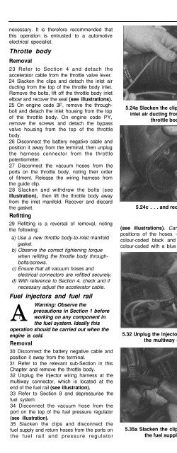
24 Slacken the clips and detach the inlet air<br />
ducting from the top of the throttle body inlet.<br />
Remove the bolts, lift off the throttle body inlet<br />
elbow and recover the seal (see illustrations).<br />
25 On engine code 3F, remove the throughbolt<br />
and detach the inlet housing from the top<br />
of the throttle body. On engine code PY,<br />
remove the screws and detach the bypass<br />
valve housing from the top of the throttle<br />
body.<br />
26 Disconnect the battery negative cable and<br />
position it away from the terminal, then unplug<br />
the harness connector from the throttle<br />
potentiometer.<br />
27 Disconnect the vacuum hoses from the<br />
ports on the throttle body, noting their order<br />
of fitment. Release the wiring harness from<br />
the guide clip.<br />
28 Slacken and withdraw the bolts (see<br />
illustration), then lift the throttle body away<br />
from the inlet manifold. Recover and discard<br />
the gasket.<br />
Refitting<br />
29 Refitting is a reversal of removal, noting<br />
the following:<br />
a) Use a new throttle body-to-inlet manifold<br />
gasket.<br />
b) Observe the correct tightening torque<br />
when refitting the throttle body throughbolts/screws.<br />
c) Ensure that all vacuum hoses and<br />
electrical connectors are refitted securely.<br />
d) With reference to Section 4, check and if<br />
necessary adjust the accelerator cable.<br />
Fuel injectors and fuel rail<br />
A<br />
Warning: Observe the<br />
precautions in Section 1 before<br />
! working on any component in<br />
the fuel system. Ideally this<br />
operation should be carried out when the<br />
engine is cold.<br />
Removal<br />
30 Disconnect the battery negative cable and<br />
position it away from the terminal.<br />
31 Refer to the relevant sub-Section in this<br />
Chapter and remove the throttle body.<br />
32 Unplug the injector wiring harness at the<br />
multiway connector, which is located at the<br />
end of the fuel rail (see illustration).<br />
33 Refer to Section 8 and depressurise the<br />
fuel system.<br />
34 Disconnect the vacuum hose from the<br />
port on the top of the fuel pressure regulator<br />
(see illustration).<br />
35 Slacken the clips and disconnect the<br />
fuel supply and return hoses from the ports on<br />
the fuel rail and pressure regulator<br />
5.24a Slacken the clips and detach the<br />
inlet air ducting from the top of the<br />
throttle body inlet<br />
5.24c . . . and recover the seal<br />
(see illustrations). Carefully note the fitted<br />
positions of the hoses - the supply hose is<br />
colour-coded black and the return hose is<br />
colour-coded with a blue band.<br />
5.32 Unplug the injector wiring harness at<br />
the multiway connector<br />
5.35a Slacken the clips and disconnect<br />
the fuel supply hose. . .<br />
5.24b Remove the bolts, lift off the throttle<br />
body inlet elbow . , .<br />
5.28 Slacken and withdraw the<br />
four throttle body retaining bolts<br />
(three arrowed, one hidden)<br />
36 Slacken and withdraw the fuel rail<br />
retaining screws, then carefully lift the fuel rail<br />
away from the inlet manifold, together with the<br />
injectors. Recover the injector lower O-ring<br />
5.34 Disconnect the vacuum hose from the<br />
top of the fuel pressure regulator<br />
5.35b . . . and return hose (arrowed)


