

Contents - Volkspage
Contents - Volkspage
Contents - Volkspage

Create successful ePaper yourself
Turn your PDF publications into a flip-book with our unique Google optimized e-Paper software.
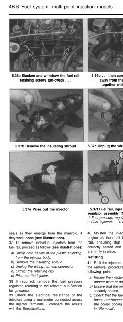
4B.6 Fuel system: multi-point injection models<br />
5.36a Slacken and withdraw the fuel rail<br />
retaining screws (art-owed) . . .<br />
5.36b . . . then carefully lift the fuel rail<br />
away from the inlet manifold,<br />
together with the injectors<br />
5.37a Unclip both halves of the plastic<br />
shielding from the injector body<br />
5.37b Remove the insulating shroud 5.37c Unplug the wiring harness connector 5.37d Extract the retaining clip<br />
5.37e Prise out the injector<br />
5.37f Fuel rail, injector and fuel pressure<br />
regulator assembly (No 1 injector removed)<br />
1 Fuel pressure regulator 2 Fuel rail<br />
3 Fuel injectors 4 Fuel pressure test point<br />
5.37g Injector O-rings (arrowed)<br />
seals as they emerge from the manifold, if<br />
they work loose (see illustrations).<br />
37 To remove individual injectors from the<br />
fuel rail, proceed as follows (see illustrations):<br />
a) Unclip both halves of the plastic shielding<br />
from the injector body.<br />
b) Remove the insulating shroud.<br />
c) Unplug the wiring harness connector.<br />
d) Extract the retaining clip.<br />
e) Prise out the injector.<br />
38 If required, remove the fuel pressure<br />
regulator, referring to the relevant sub-Section<br />
for guidance.<br />
39 Check the electrical resistance of the<br />
injectors using a multimeter connected across<br />
the injector terminals - compare the results<br />
with the Specifications.<br />
40 Moisten the injector O-rings with clean<br />
engine oil, then refit the injectors to the fuel<br />
rail, ensuring that the O-ring seals are<br />
correctly seated and that the retaining clips<br />
are firmly in place.<br />
Refitting<br />
41 Refit the injectors and fuel rail by following<br />
the removal procedure in reverse, noting the<br />
following points:<br />
a) Renew the injector O-ring seals if they<br />
appear worn or damaged.<br />
b) Ensure that the injector retaining clips are<br />
securely seated.<br />
c) Check that the fuel supply and return<br />
hoses are reconnected correctly - refer to<br />
the colour coding described<br />
in “Removal”.<br />
d) Check that all vacuum and electrical<br />
connections are remade correctly and<br />
securely.<br />
e) On completion, check exhaustively for<br />
fuel leaks before bringing the vehicle back<br />
in to service.<br />
Fuel pressure regulator<br />
A<br />
Warning: Observe the<br />
precautions in Section 1 before<br />
! working on the fuel system.<br />
ideally this operation should be<br />
carried out when the engine is cold.<br />
Removal<br />
42 Disconnect the battery negative cable and<br />
position it away from the terminal.<br />
43 Refer to Section 8 and depressurise the<br />
fuel system.


