

Contents - Volkspage
Contents - Volkspage
Contents - Volkspage

You also want an ePaper? Increase the reach of your titles
YUMPU automatically turns print PDFs into web optimized ePapers that Google loves.
6.2 Clutch<br />
Refitting<br />
5 Refitting is a reversal of removal, but note<br />
the following points:<br />
a) Make sure the flats on the cable are located<br />
correctly on the steering gear housing.<br />
b) Grease the cable attachment point on the<br />
pedal, but do not grease the cable before<br />
fitting it to the steering gear housing, as<br />
there is a danger of grease blocking the<br />
breather vent.<br />
c) Check that the clutch operates correctly:<br />
depress the pedal several times, then pull<br />
the release lever approximately 10 mm<br />
away from the cable to check that it is free.<br />
Removal<br />
1 Disconnect the clutch cable from the<br />
release arm on the transmission clutch<br />
housing and from the top of the clutch pedal<br />
with reference to Section 3.<br />
2 Prise the clip from the end of the pedal<br />
pivot shaft.<br />
3 On left-hand drive models, withdraw the<br />
pivot shaft just enough to allow the clutch<br />
pedal to be removed from the bracket. On<br />
right-hand drive models, the pivot shaft must<br />
first be withdrawn through the brake pedal.<br />
4 Clean the pedal and pivot shaft and<br />
examine them for wear. If the bushes are worn<br />
they can be removed using a soft metal drift,<br />
and the new bushes installed using a vice to<br />
press then into position. Check the rubber<br />
foot pad and the stop rubber on the bracket,<br />
and renew them if necessary.<br />
Refitting<br />
5 Refitting is a reversal of removal, but apply<br />
a little multi-purpose grease to the pivot shaft<br />
and bushes.<br />
torsional damping springs and protrudes by a<br />
greater amount - this side faces the pressure<br />
plate.<br />
5 Check the condition of the clutch<br />
components as described in the following<br />
sub-Section.<br />
Inspection<br />
6 Examine the surfaces of the pressure plate<br />
and flywheel for signs of heavy scoring. Light<br />
scoring is normal, but if excessive the<br />
pressure plate must be renewed and the<br />
flywheel either machined or renewed.<br />
7 Inspect the ends of the pressure plate<br />
diaphragm spring fingers; look for wear<br />
caused by contact with the release bearing. If<br />
the scoring appears excessive, renew the<br />
assembly.<br />
8 Using a straight edge and feeler blade,<br />
check that the inward taper of the pressure<br />
plate does not exceed the maximum amount<br />
given in the Specifications (see illustration).<br />
Also check for loose riveted joints and for any<br />
cracks in the pressure plate components.<br />
9 Check the driven plate linings for wear; renew<br />
the plate if the linings are worn to within 1.0 mm<br />
(0.04in) of the lining material securing rivets.<br />
10 Check that the driven plate damper<br />
springs and all rivets are secure, and that the<br />
linings are not contaminated with oil.<br />
Temporarily fit the disc to the transmission<br />
input shaft and check that the run-out does<br />
not exceed that given in the Specifications.<br />
11 If the clutch components are<br />
contaminated with oil, the leak should be<br />
found and rectified. The procedure for<br />
renewing the crankshaft oil seal is described<br />
in Chapter 2A; the procedure for renewing the<br />
transmission input shaft oil seal is described<br />
in Chapter 7.<br />
12 Having checked the clutch disc and<br />
pressure plate, check the release bearing with<br />
reference to Section 7.<br />
Refitting<br />
13 Before commencing the refitting<br />
procedure, a tool must be obtained for<br />
aligning the driven plate, otherwise difficulty<br />
will be experienced when refitting the<br />
transmission. If the driven plate is not aligned<br />
centrally before the pressure plate is fitted, it<br />
will not be possible to engage the<br />
transmission input shaft with it. If a<br />
centralising tool is not available, a wooden<br />
mandrel may be made to the dimensions<br />
shown (see illustration).<br />
14 Clean the friction faces of the flywheel<br />
and pressure plate, then fit the centralising<br />
tool to the crankshaft and locate the driven<br />
plate on it with the hub extension facing<br />
outwards (see illustration).<br />
15 Fit the pressure plate assembly to the<br />
flywheel (using the alignment marks made<br />
during removal, if the original component is<br />
being refitted). Ensure that the friction surface<br />
lies flat against the driven plate, then insert<br />
the retaining bolts and tighten them<br />
progressively in diagonal sequence to the<br />
specified torque (see illustration).<br />
16 Refit the transmission as described in<br />
Chapter 7, then reconnect the clutch cable as<br />
described in Section 2.<br />
Removal<br />
1 Remove the transmission as described in<br />
Chapter 7.<br />
2 Mark the position of the pressure plate<br />
cover with respect to the flywheel, to ensure<br />
correct alignment on refitting.<br />
3 Using an Allen key or hex bit, unscrew the<br />
pressure plate bolts progressively in a<br />
diagonal sequence (see illustration). If<br />
necessary, prevent the flywheel from rotating<br />
by inserting a screwdriver between the starter<br />
ring gear teeth and the cylinder block.<br />
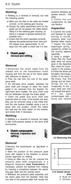
4 Withdraw the pressure plate assembly and<br />
the driven plate from the flywheel. Note that<br />
one side of the pressure plate hub houses the<br />
4.3 Removing the pressure plate bolts 4.8 Checking the clutch pressure plate<br />
for taper<br />
4.13 Clutch driven plate centralising tool<br />
dimensions<br />
A 18.24 mm B 70.0mm<br />
C 20.0mm D 14.81 mm<br />
4.14 Driven plate fitted<br />
with centralising tool in place


