

Contents - Volkspage
Contents - Volkspage
Contents - Volkspage

You also want an ePaper? Increase the reach of your titles
YUMPU automatically turns print PDFs into web optimized ePapers that Google loves.
8.4 Driveshafts<br />
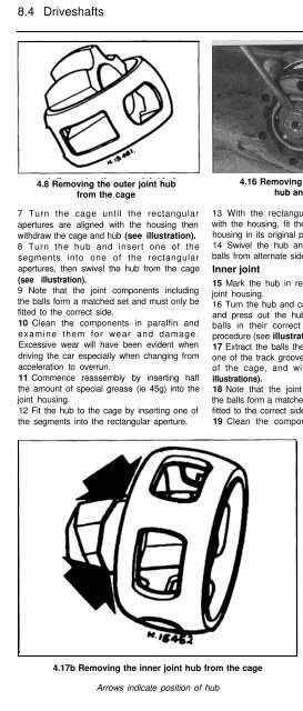
4.8 Removing the outer joint hub<br />
from the cage<br />
7 Turn the cage until the rectangular<br />
apertures are aligned with the housing then<br />
withdraw the cage and hub (see illustration).<br />
8 Turn the hub and insert one of the<br />
segments into one of the rectangular<br />
apertures, then swivel the hub from the cage<br />
(see illustration).<br />
9 Note that the joint components including<br />
the balls form a matched set and must only be<br />
fitted to the correct side.<br />
10 Clean the components in paraffin and<br />
examine them for wear and damage.<br />
Excessive wear will have been evident when<br />
driving the car especially when changing from<br />
acceleration to overrun.<br />
11 Commence reassembly by inserting half<br />
the amount of special grease (ie 45g) into the<br />
joint housing.<br />
12 Fit the hub to the cage by inserting one of<br />
the segments into the rectangular aperture.<br />
4.16 Removing the inner joint<br />
hub and cage<br />
13 With the rectangular apertures aligned<br />
with the housing, fit the hub and cage to the<br />
housing in its original position.<br />
14 Swivel the hub and cage and insert the<br />
balls from alternate sides.<br />
Inner joint<br />
15 Mark the hub in relation to the cage and<br />
joint housing.<br />
16 Turn the hub and cage 90° to the housing<br />
and press out the hub and cage. Keep the<br />
balls in their correct positions during this<br />
procedure (see illustration).<br />
17 Extract the balls then turn the hub so that<br />
one of the track grooves is located on the rim<br />
of the cage, and withdraw the hub (see<br />
illustrations).<br />
18 Note that the joint components including<br />
the balls form a matched set and must only be<br />
fitted to the correct side.<br />
19 Clean the components in paraffin and<br />
4.17a Inner joint hub, cage and housing<br />
examine them for wear and damage.<br />
Excessive wear will have been evident when<br />
driving the car especially when changing from<br />
acceleration to overrun.<br />
20 Commence reassembly by fitting the hub<br />
to the cage.<br />
21 Insert the balls into position using the<br />
special grease to hold them in place.<br />
22 Press the hub and cage into the housing<br />
making sure that the wide track spacing on<br />
the housing will be adjacent to the narrow<br />
spacing on the hub (see illustration) when<br />
fully assembled. Note also that the chamfer<br />
on the hub splines must face the large<br />
diameter side of the housing.<br />
23 Swivel the cage ahead of the hub so that<br />
the balls enter their respective tracks then<br />
align the hub and cage with the housing.<br />
24 Check that the hub can be moved freely<br />
through its operating arc.<br />
4.17b Removing the inner joint hub from the cage<br />
Arrows indicate position of hub<br />
4.22 Assembly of the inner joint cage and hub to the housing<br />
“a” must be aligned with “b”


