

Contents - Volkspage
Contents - Volkspage
Contents - Volkspage

You also want an ePaper? Increase the reach of your titles
YUMPU automatically turns print PDFs into web optimized ePapers that Google loves.
2B.10 Engine removal and overhaul procedures<br />
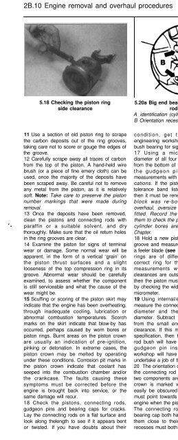
5.18 Checking the piston ring<br />
side clearance<br />
5.20a Big end bearing cap and connecting<br />
rod markings<br />
A identification (cylinder number) markings<br />
B Orientation recesses<br />
5.20b Orientation arrow on piston crown<br />
(highlighted)<br />
11 Use a section of old piston ring to scrape<br />
the carbon deposits out of the ring grooves,<br />
taking care not to score or gouge the edges of<br />
the groove.<br />
12 Carefully scrape away all traces of carbon<br />
from the top of the piston. A hand-held wire<br />
brush (or a piece of fine emery cloth) can be<br />
used, once the majority of the deposits have<br />
been scraped away. Be careful not to remove<br />
any metal from the piston, as it is relatively<br />
soft. Note: Take care to preserve the piston<br />
number markings that were made during<br />
removal.<br />
13 Once the deposits have been removed,<br />
clean the pistons and connecting rods with<br />
paraffin or a suitable solvent, and dry<br />
thoroughly. Make sure that the oil return holes<br />
in the ring grooves are clear.<br />
14 Examine the piston for signs of terminal<br />
wear or damage. Some normal wear will be<br />
apparent, in the form of a vertical ‘grain’ on<br />
the piston thrust surfaces and a slight<br />
looseness of the top compression ring in its<br />
groove. Abnormal wear should be carefully<br />
examined, to assess whether the component<br />
is still serviceable and what the cause of the<br />
wear might be.<br />
15 Scuffing or scoring of the piston skirt may<br />
indicate that the engine has been overheating,<br />
through inadequate cooling, lubrication or<br />
abnormal combustion temperatures. Scorch<br />
marks on the skirt indicate that blow-by has<br />
occurred, perhaps caused by worn bores or<br />
piston rings. Burnt areas on the piston crown<br />
are usually an indication of pre-ignition,<br />
pinking or detonation. In extreme cases, the<br />
piston crown may be melted by operating<br />
under these conditions. Corrosion pit marks in<br />
the piston crown indicate that coolant has<br />
seeped into the combustion chamber and/or<br />
the crankcase. The faults causing these<br />
symptoms must be corrected before the<br />
engine is brought back into service, or the<br />
same damage will recur.<br />
18 Check the pistons, connecting rods,<br />
gudgeon pins and bearing caps for cracks.<br />
Lay the connecting rods on a flat surface and<br />
look along thelength to see if it appears bent<br />
or twisted. If you have doubts about their<br />
condition, get them measured at an<br />
engineering workshop. Inspect the small end<br />
bush bearing for signs of wear or cracking.<br />
17 Using a micrometer, measure the<br />
diameter of all four pistons at a point 10 mm<br />
from the bottom of the skirt, at right angles to<br />
the gudgeon pin axis. Compare the<br />
measurements with those listed in the Specifications.<br />
If the piston diameter is out of the<br />
tolerance band listed for its particular size,<br />
then it must be renewed. Note: If the cylinder<br />
block was re-bored during a previous<br />
overhaul, oversize pistons may have been<br />
fitted. Record the measurements and use<br />
them to check the piston clearances when the<br />
cylinder bores are measured, later in this<br />
Chapter.<br />
18 Hold a new piston ring in the appropriate<br />
groove and measure the side clearance using<br />
a feeler blade (see illustration). Note that the<br />
rings are of different widths, so use the<br />
correct ring for the groove. Compare the<br />
measurements with those listed; if the<br />
clearances are outside of the tolerance band,<br />
then the piston must be renewed. Confirm this<br />
by checking the width of the piston ring with a<br />
micrometer.<br />
19 Using internal/external vernier callipers,<br />
measure the connecting rod small end internal<br />
diameter and the gudgeon pin external<br />
diameter. Subtract the gudgeon pin diameter<br />
from the small end diameter to obtain the<br />
clearance. If this measurement is outside its<br />
specification, then the piston and connecting<br />
rod bush will have to be resized and a new<br />
gudgeon pin installed. An engineering<br />
workshop will have the equipment needed to<br />
undertake a job of this nature.<br />
20 The orientation of the piston with respect to<br />
the connecting rod must be correct when the<br />
two components are reassembled. The piston<br />
crown is marked with an arrow (which can<br />
easily be obscured by carbon deposits); this<br />
must point towards the timing belt end of the<br />
engine when the piston is installed in the bore.<br />
The connecting rod and its corresponding<br />
bearing cap both have recesses machined into<br />
them close to their mating surfaces - these<br />
recesses must both face in the same direction<br />
as the arrow on the piston crown (ie towards the<br />
timing belt end of the engine) when correctly<br />
installed (see illustrations). Reassemble the<br />
two components to satisfy this requirement.<br />
21 Lubricate the gudgeon pin and small end<br />
bush with clean engine oil. Slide the pin into<br />
the piston, engaging the connecting rod small<br />
end. Fit two new circlips to the piston at either<br />
end of the gudgeon pin, so that their open<br />
ends are facing 180° away from the removal<br />
slot in the piston. Repeat this operation for the<br />
remaining pistons.<br />
Removal<br />
1 Note: If no work is to be done on the<br />
pistons and connecting rods, then removal the<br />
cylinder head and pistons will not be<br />
necessary. Instead, the pistons need only be<br />
pushed far enough up the bores so that they<br />
are positioned clear of the crankpins. The use<br />
of an engine stand is strongly recommended.<br />
2 With reference to Chapter 2A, carry out the<br />
following:<br />
a) Remove the crankshaft timing belt<br />
sprocket.<br />
b) Remove the clutch components and<br />
flywheel.<br />
c) Remove the sump, baffle plate, oil pump<br />
and pickup.<br />
d) Remove the front and rear crankshaft oil<br />
seals and their housings.<br />
3 Unbolt the pistons and connecting rods<br />
from the crankpins, as described in Section 5<br />
(refer to the Note above).<br />
4 Carry out a check of the crankshaft endfloat,<br />
as follows. Note: This can only be<br />
accomplished when the crankshaft is still<br />
installed in the cylinder block/crankcase, but is<br />
free to move. Set up a DTI gauge so that the<br />
probe is in line with the crankshaft axis and is<br />
in contact with a fixed point on end of the<br />
crankshaft. Push the crankshaft along its axis<br />
to the end of its travel, and then zero the


