

Contents - Volkspage
Contents - Volkspage
Contents - Volkspage

Create successful ePaper yourself
Turn your PDF publications into a flip-book with our unique Google optimized e-Paper software.
4B.4 Fuel system: multi-point injection models<br />
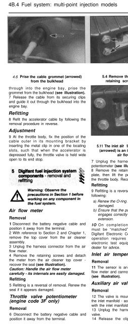
4.6 Prise the cable grommet (arrowed)<br />
from the bulkhead<br />
5.4 Remove the air flow meter<br />
retaining screws (at-rowed)<br />
5.7 Unplug the wiring harness from the<br />
potentiometer at the connector (arrowed)<br />
through into the engine bay, prise the<br />
grommet from the bulkhead (see illustration).<br />
7 Release the cable from its securing clips<br />
and guide it out through the bulkhead into the<br />
engine bay.<br />
Refitting<br />
8 Refit the accelerator cable by following the<br />
removal procedure in reverse.<br />
Adjustment<br />
9 At the throttle body, fix the position of the<br />
cable outer in its mounting bracket by<br />
inserting the metal clip in one of the locating<br />
slots, such that when the accelerator is<br />
depressed fully, the throttle valve is held wide<br />
open to its end stop.<br />
Air flow meter<br />
Removal<br />
1 Disconnect the battery negative cable and<br />
position it away from the terminal.<br />
2 With reference to Section 2 and Chapter 1,<br />
remove the top cover from the air cleaner<br />
assembly.<br />
3 Unplug the harness connector from the air<br />
flow meter.<br />
4 Remove the retaining screws and detach<br />
the meter from the air cleaner top cover -<br />
recover the seal (see illustration).<br />
Caution: Handle the air flow meter<br />
carefully - its internals are easily damaged.<br />
Refitting<br />
5 Refitting is a reversal of removal. Renew the<br />
seal if it appears damaged.<br />
Throttle valve potentiometer<br />
(engine code 3F only)<br />
Removal<br />
6 Disconnect the battery negative cable and<br />
position it away from the terminal.<br />
5.11 The inlet air temperature sensor<br />
(arrowed) is an integral part of the<br />
air flow meter<br />
7 Unplug the harness connector from the<br />
potentiometer (see illustration).<br />
8 Remove the retaining screws and locking<br />
plate, then lift the potentiometer away from<br />
the throttle body. Recover the O-ring seal.<br />
Refitting<br />
9 Refitting is a reversal of removal, noting the<br />
following:<br />
a) Renew the O-ring seal if it appears<br />
damaged.<br />
b) Ensure that the potentiometer drive<br />
engages correctly with the throttle spindle<br />
extension.<br />
IO On completion, the potentiometer<br />
must be “matched” electronically to the<br />
Digifant Electronic Control Unit (ECU). This<br />
operation requires access to dedicated<br />
electronic test equipment, refer to a VW<br />
dealer for advice.<br />
Inlet air temperature sensor<br />
Removal<br />
11 The sensor is an integral part of the air<br />
flow meter and cannot be renewed separately<br />
(see illustration).<br />
Auxiliary air valve<br />
Removal<br />
12 The valve is mounted on a bracket below<br />
the inlet manifold - access is extremely limited<br />
with the inlet manifold in position.<br />
13 Unplug the harness connector from the<br />
valve.<br />
14 Release the clips and disconnect the<br />
5.17 Two coolant temperature sensors are<br />
fitted; the one colour coded blue (arrowed)<br />
serves the engine management system<br />
hoses from the auxiliary valve. Note their<br />
order of connection to aid correct refitting.<br />
15 Remove the screw and detach the valve<br />
from its mountings.<br />
Refitting<br />
16 Refitting is a reversal of removal.<br />
Coolant temperature sensor<br />
Removal<br />
17 The coolant temperature sensor is<br />
mounted at the left hand side of the cylinder<br />
head, directly underneath the ignition<br />
distributor. Two sensors are fitted; the one<br />
colour coded blue serves the engine<br />
management system, the black one produces<br />
a signal for the instrument panel temperature<br />
gauge (see illustration).<br />
18 Unplug the harness connector from the<br />
sensor.<br />
19 Refer to Chapter 3 and drain<br />
approximately one quarter of the coolant from<br />
the engine.<br />
20 Extract the retaining clip and lift the<br />
sensor from the coolant elbow - be prepared<br />
for coolant loss. Recover the O-ring.<br />
Refitting<br />
21 Refit the sensor by reversing the removal<br />
procedure, using a new O-ring. Refer to<br />
Chapter 1 and top-up the cooling system.<br />
Engine speed Hall sender<br />
22 This sensor is an integral part of the<br />
ignition HT distributor assembly. It can be<br />
removed and renewed separately, but<br />
dismantling of the distributor will be


