

Contents - Volkspage
Contents - Volkspage
Contents - Volkspage

You also want an ePaper? Increase the reach of your titles
YUMPU automatically turns print PDFs into web optimized ePapers that Google loves.
9.6 Braking system<br />
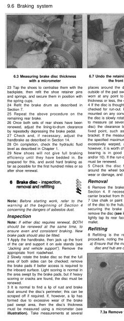
6.3 Measuring brake disc thickness<br />
with a micrometer<br />
6.7 Undo the retaining screw and remove<br />
the front brake disc<br />
7.2 Lever out and remove the cap from the<br />
centre of the brake drum<br />
23 Tap the shoes to centralise them with the<br />
backplate, then refit the shoe retainer pins<br />
and springs, and secure them in position with<br />
the spring cups.<br />
24 Refit the brake drum as described in<br />
Section 7.<br />
25 Repeat the above procedure on the<br />
remaining rear brake.<br />
26 Once both sets of rear shoes have been<br />
renewed, adjust the lining-to-drum clearance<br />
by repeatedly depressing the brake pedal.<br />
27 Check and, if necessary, adjust the<br />
handbrake as described in Section 14.<br />
28 On completion, check the hydraulic fluid<br />
level as described in Chapter 1.<br />
29 New shoes will not give full braking<br />
efficiency until they have bedded in. Be<br />
prepared for this, and avoid hard braking as<br />
far as possible for the first hundred miles or so<br />
after shoe renewal.<br />
Note: Before starting work, refer to the<br />
warning at the beginning of Section 4<br />
concerning the dangers of asbestos dust.<br />
Inspection<br />
Note: If either disc requires renewal, BOTH<br />
should be renewed at the same time, to<br />
ensure even and consistent braking. New<br />
brake pads should also be fitted.<br />
1 Apply the handbrake, then jack up the front<br />
of the car and support it on axle stands (see<br />
“Jacking and vehicle support”). Remove the<br />
appropriate front roadwheel.<br />
2 Slowly rotate the brake disc so that the full<br />
area of both sides can be checked; remove<br />
the brake pads if better access is required to<br />
the inboard surface. Light scoring is normal in<br />
the area swept by the brake pads, but if heavy<br />
scoring or cracks are found, the disc must be<br />
renewed.<br />
3 It is normal to find a lip of rust and brake<br />
dust around the disc’s perimeter; this can be<br />
scraped off if required. If, however, a lip has<br />
formed due to excessive wear of the brake<br />
pad swept area, then the disc’s thickness<br />
must be measured using a micrometer (see<br />
illustration). Take measurements at several<br />
places around the disc, at the inside and<br />
outside of the pad swept area; if the disc has<br />
worn at any point to the specified minimum<br />
thickness or less, the disc must be renewed.<br />
4 If the disc is thought to be warped, it can be<br />
checked for run-out. Either use a dial gauge<br />
mounted on any convenient fixed point, while<br />
the disc is slowly rotated, or use feeler blades<br />
to measure (at several points all around the<br />
disc) the clearance between the disc and a<br />
fixed point, such as the caliper mounting<br />
bracket. If the measurements obtained are at<br />
the specified maximum or beyond, the disc is<br />
excessively warped, and must be renewed;<br />
however, it is worth checking first that the hub<br />
bearing is in good condition (Chapters 1<br />
and/or 10). If the run-out is excessive, the disc<br />
must be renewed.<br />
5 Check the disc for cracks, especially<br />
around the wheel bolt holes, and any other<br />
wear or damage, and renew if necessary.<br />
Removal<br />
6 Remove the brake pads as described in<br />
Section 4. If necessary unbolt the caliper<br />
carrier bracket from the swivel hub.<br />
7 Use chalk or paint to mark the relationship<br />
of the disc to the hub, then remove the screw<br />
securing the brake disc to the hub, and<br />
remove the disc (see illustration). If it is tight,<br />
lightly tap its rear face with a hide or plastic<br />
mallet.<br />
Refitting<br />
8 Refitting is the reverse of the removal<br />
procedure, noting the following points:<br />
a) Ensure that the mating surfaces of the<br />
disc and hub are clean and flat.<br />
b) Align (if applicable) the marks made on<br />
removal, and secure/y tighten the disc<br />
retaining screw.<br />
c) If a new disc has been fitted, use a<br />
suitable solvent to wipe any preservative<br />
coating from the disc, before refitting the<br />
caliper.<br />
d) Refit the pads as described in Section 4.<br />
e) Refit the roadwheel, then lower the car to<br />
the ground and tighten the roadwheel<br />
bolts to the specified torque. On<br />
completion, repeatedly depress the brake<br />
pedal until normal pedal pressure returns.<br />
Note: Before starting work, refer to the<br />
warning at the beginning of Section 5<br />
concerning the dangers of asbestos dust.<br />
Removal<br />
1 Chock the front wheels, then jack up the<br />
rear of the vehicle and support it on axle<br />
stands (see “Jacking and vehicle support”).<br />
Remove the appropriate rear wheel. Release<br />
the handbrake lever.<br />
2 Using a hammer and a large flat-bladed<br />
screwdriver, carefully tap and prise the cap<br />
out of the centre of the brake drum (see<br />
illustration). Discard the cap if it is disfigured<br />
during removal.<br />
3 Extract the split pin and remove the locking<br />
cap (see illustrations). Discard the split pin; a<br />
new one must be used on refitting.<br />
7.3a Remove the split pin . . . 7.3b . . . and locking cap.. .


