

Contents - Volkspage
Contents - Volkspage
Contents - Volkspage

You also want an ePaper? Increase the reach of your titles
YUMPU automatically turns print PDFs into web optimized ePapers that Google loves.
2B.8 Engine removal and overhaul procedures<br />
into position using a long reach socket<br />
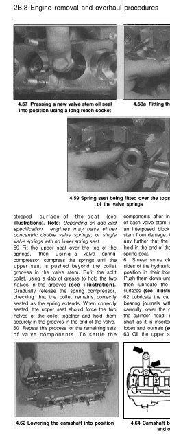
4.59 Spring seat being fitted over the tops<br />
of the valve springs<br />
4.61 Refitting the hydraulic tappets<br />
stepped surface of the seat (see<br />
illustrations). Note: Depending on age and<br />
specification, engines may have either<br />
concentric double valve springs, or single<br />
valve springs with no lower spring seat.<br />
59 Fit the upper seat over the top of the<br />
springs, then using a valve spring<br />
compressor, compress the springs until the<br />
upper seat is pushed beyond the collet<br />
grooves in the valve stem. Refit the split<br />
collet, using a dab of grease to hold the two<br />
halves in the grooves (see illustration).<br />
Gradually release the spring compressor,<br />
checking that the collet remains correctly<br />
seated as the spring extends. When correctly<br />
seated, the upper seat should force the two<br />
halves of the collet together and hold them<br />
securely in the grooves in the end of the valve.<br />
60 Repeat this process for the remaining sets<br />
of valve components. To settle the<br />
components after installation, strike the end<br />
of each valve stem lightly with a mallet, using<br />
an interposed block of wood to protect the<br />
stem from damage. Check before progressing<br />
any further that the split collets remain firmly<br />
held in the end of the valve stem by the upper<br />
spring seat.<br />
61 Smear some clean engine oil onto the<br />
sides of the hydraulic tappets and fit them into<br />
position in their bores in the cylinder head.<br />
Push them down until they contact the valves,<br />
then lubricate the camshaft lobe contact<br />
surfaces (see illustration).<br />
62 Lubricate the camshaft and cylinder head<br />
bearing journals with clean engine oil, then<br />
carefully lower the camshaft into position on<br />
the cylinder head. Support the ends of the<br />
shaft as it is inserted, to avoid damaging the<br />
lobes and journals (see illustration).<br />
63 Oil the upper surfaces of the camshaft<br />
bearing journals, then fit the bearing caps in<br />
place. Ensure that they are fitted the right way<br />
around and in the correct locations, then fit<br />
and tighten the retaining nuts, as follows:<br />
64 The bearing caps have their respective<br />
cylinder numbers stamped onto them and<br />
have an elongated lug on one side. When<br />
correctly fitted, the numbers should be<br />
readable from the exhaust side of the cylinder<br />
head and the lugs should face the inlet side of<br />
the cylinder head (see illustration).<br />
65 Fit caps Nos 2 and 4 over the camshaft<br />
and tighten the retaining nuts alternately and<br />
diagonally to the specified first stage torque<br />
(see illustration).<br />
66 Smear the cylinder head mating surfaces<br />
of caps Nos 1 and 5 with suitable sealant then<br />
fit them, together with cap No 3, over the<br />
camshaft and tighten the nuts to the specified<br />
first stage torque.<br />
4.62 Lowering the camshaft into position 4.64 Camshaft bearing cap markings 4.65 Tightening the camshaft<br />
and orientation<br />
bearing cap nuts


