

Contents - Volkspage
Contents - Volkspage
Contents - Volkspage

Create successful ePaper yourself
Turn your PDF publications into a flip-book with our unique Google optimized e-Paper software.
10.8 Suspension and steering<br />
13.3a Unscrew the nut. . . 13.3b . . . and remove the washer<br />
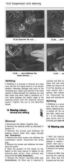
14.3a Remove the screws. . .<br />
14.3b . . . and withdraw the<br />
lower shroud . . .<br />
14.3c . . . and upper shroud<br />
Refitting<br />
4 Refitting in a reversal of removal, but make<br />
sure that the turn signal lever is in its neutral<br />
position, otherwise damage may occur to the<br />
cancelling arm. Make sure that the 3 mm thick<br />
washer is fitted beneath the retaining nut, and<br />
also check that when fitted a clearance of 3<br />
mm exists between the bottom edge of the<br />
steering wheel and the steering column<br />
switch. Tighten the nut to the specified<br />
torque.<br />
Removal<br />
1 Disconnect the battery negative lead.<br />
2 Remove the steering wheel as described in<br />
Section 13.<br />
3 Remove the screws and withdraw the<br />
steering column lower then upper shrouds<br />
(see illustrations).<br />
4 Remove the three screws and withdraw the<br />
combination switch. Disconnect the wiring<br />
plug.<br />
5 Remove the screws and withdraw the lower<br />
facia trim panel.<br />
6 Mark the position of the clamp on the<br />
bottom of the inner column in relation to the<br />
steering gear pinion, then unscrew and<br />
remove the bolt (see illustration).<br />
7 Remove the column mounting bolts (see<br />
illustration). An Allen key is required to<br />
unscrew one bolt, but the remaining bolt is a<br />
shear bolt and therefore its head must be<br />
drilled out using an 8.5 mm diameter drill.<br />
8 Lift the steering column and disconnect the<br />
inner column from the steering gear pinion<br />
splines, then withdraw the column from the<br />
car. Disconnect the ignition switch wiring<br />
plug, and unscrew the old shear bolt.<br />
Refitting<br />
9 Refitting is a reversal of removal, but make<br />
sure that the column is correctly positioned<br />
before tightening the shear bolt until its head<br />
is broken off. On models manufactured from<br />
late 1991, make sure that there is a clearance<br />
of 1 .0 mm between the end of the steering<br />
gear pinion and the adjacent part of the<br />
universal joint (see illustration).<br />
1 With the steering column removed as<br />
described in Section 14 mark the splined<br />
adapter in relation to the top of the inner<br />
column, then use a suitable puller to remove<br />
the adapter (see illustration).<br />
2 Remove the spring from the top of the inner<br />
column.<br />
3 Using an Allen key unscrew the clamp bolt<br />
securing the steering lock and withdraw the<br />
lock. Note that the ignition key must be<br />
inserted and the lock released.<br />
14.7 Steering column mounting bolts<br />
14.9 On later models make sure that the<br />
clearance shown is maintained between<br />
the end of the steering gear pinion and the<br />
universal joint


