Contents - Volkspage
Contents - Volkspage
Contents - Volkspage
Create successful ePaper yourself
Turn your PDF publications into a flip-book with our unique Google optimized e-Paper software.
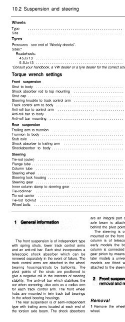
10.2 Suspension and steering<br />
Wheels<br />
Type ................................................. Pressed steel disc or alloy<br />
Size ................................................. 45J x 13 or 55J x 13<br />
Tyres<br />
Pressures - see end of “Weekly checks”.<br />
Sizes:*<br />
Roadwheels:<br />
45Jx13 ............................................. 135 R 13,145 R 13 or 155/70 R 13<br />
5.5Jx13 ............................................. 165/65 R 13 or 175/60 R 13<br />
‘Consult your handbook, a VW dealer or a tyre dealer for the correct size for your vehicle.<br />
Torque wrench settings Nm Ibf ft<br />
Front suspension<br />
Strut to body ............................................. 60 44<br />
Shock absorber rod to top mounting .......................... 50 37<br />
Strut cap ................................................. 150 110<br />
Steering knuckle to track control arm .......................... 50 37<br />
Track control arm to body ................................... 55 41<br />
Anti-roll bar to control arm ................... -. ............. 75 55<br />
Anti-roll bar to body ........................................ 30 22<br />
Anti-roll bar mounting ...................................... 120 89<br />
Rear suspension<br />
Trailing arm to trunnion . , .................................... 40 30<br />
Trunnion to body .......................................... 120 89<br />
Stub axle ................................................ 60 44<br />
Shock absorber to trailing arm ............................... 45 33<br />
Shockabsorber to body ..................................... 20 15<br />
Steering<br />
Tie-rod (outer) ............................................ 35 26<br />
Flange tube ............................................... 25 18<br />
Column tube ............................................. 20 15<br />
Steering wheel ............................................ 50 37<br />
Steering lock housing ....................................... 10 7<br />
Steering gear ............................................. 25 18<br />
Inner column clamp to steering gear ........................... 30 22<br />
Tie-rodinner ............................................. 30 22<br />
Tie-rod carrier ............................................ 40 30<br />
Tie-rod locknut ........................................... 40 30<br />
Wheel bolts .............................................. 110 81<br />
The front suspension is of independent type<br />
with spring struts, lower track control arms<br />
and an anti-roll bar. Each strut incorporates a<br />
telescopic shock absorber which can be<br />
renewed separately in the event of failure. The<br />
track control arms are attached to the wheel<br />
bearing housings/struts by balljoints. The<br />
pivot points of the struts are positioned to<br />
give a negative roll in the interests of steering<br />
stability. The anti-roll bar which stabilises the<br />
car when cornering, also acts as a radius arm<br />
for each track control arm. The front wheel<br />
hubs are mounted in twin track ball bearings<br />
in the wheel bearing housings.<br />
The rear suspension is of semi-independent<br />
type with trailing arms located at each end of<br />
the torsion axle beam. The shock absorbers<br />
are an integral part of the spring struts. The<br />
axle beam is attached to the trailing arms<br />
behind the pivot points.<br />
The steering is of rack and pinion type<br />
mounted on the front of the bulkhead, and the<br />
column is of telescopic (safety) design. On<br />
early models the bottom end of the inner<br />
column is connected directly to the steering<br />
gear pinion by means of a clamp, however on<br />
later models a universal joint is fitted. Some<br />
models are fitted with a steering damper<br />
attached to the steering gear end fitting.<br />
Removal<br />
1 Remove the wheel trim from the relevant<br />
wheel.<br />
2 With the handbrake applied loosen the<br />
driveshaft nut (see illustration). The nut is<br />
tightened to a high torque and a socket<br />
extension may be required.<br />
3 Jack up the front of the car and support it<br />
on axle stands (see “Jacking and vehicle<br />
support”). Remove the roadwheel.<br />
2.2 Driveshaft nut


