

Contents - Volkspage
Contents - Volkspage
Contents - Volkspage

Create successful ePaper yourself
Turn your PDF publications into a flip-book with our unique Google optimized e-Paper software.
8.2 Driveshafts<br />
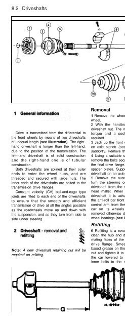
1 .1 Exploded view of the<br />
right-hand driveshaft<br />
1 Circlip<br />
2 Inner cons tan t<br />
velocity joint<br />
3 Dished washer<br />
4 Protective cap<br />
5 Rubber gaiter<br />
6 Balance weight<br />
7 Shaft<br />
8 Dished washer<br />
9 Circlip<br />
10 Clip<br />
11 Rubber gaiter<br />
12 Hose clip<br />
13 Outer constant<br />
velocity joint<br />
Drive is transmitted from the differential to<br />
the front wheels by means of two driveshafts<br />
of unequal length (see illustration). The righthand<br />
driveshaft is longer than the left-hand,<br />
due to the position of the transmission. The<br />
left-hand driveshaft is of solid construction<br />
and the right-hand one is of tubular<br />
construction.<br />
Both driveshafts are splined at their outer<br />
ends to enter the wheel hubs, and are<br />
threaded and secured with large nuts. The<br />
inner ends of the driveshafts are bolted to the<br />
transmission drive flanges.<br />
Constant velocity (CV) ball-and-cage type<br />
joints are fitted to each end of the driveshafts<br />
to ensure that the smooth and efficient<br />
transmission of drive at all the angles possible<br />
as the roadwheels move up and down with<br />
the suspension, and as they turn from side to<br />
side under steering.<br />
Note: A new driveshaft retaining nut will be<br />
required on refitting.<br />
Removal<br />
1 Remove the wheel trim from the relevant<br />
wheel.<br />
2 With the handbrake applied loosen the<br />
driveshaft nut. The nut is tightened to a high<br />
torque and a socket extension may be<br />
required.<br />
3 Jack up the front of the car and support it<br />
on axle stands (see “Jacking and vehicle<br />
support”). Remove the roadwheel.<br />
4 Using a suitable splined key, unscrew and<br />
remove the bolts securing the inner CV joint to<br />
the final drive flange. Note the location of the<br />
spacer plates. Support the inner end of the<br />
driveshaft on an axle stand.<br />
5 Remove the outer nut and washer, then<br />
turn the steering on full lock and tap the<br />
driveshaft from the splined hub using a soft<br />
head mallet. When removing the right-hand<br />
driveshaft it is advantageous to disconnect<br />
the anti-roll bar front mountings and the track<br />
control arm from the strut. Do not move the<br />
car on its wheels with either driveshaft<br />
removed otherwise damage may occur to the<br />
wheel bearings (see illustration).<br />
Refitting<br />
6 Refitting is a reversal of removal, but first<br />
clean the hub and driveshaft splines and the<br />
mating faces of the inner CV joint and final<br />
drive flange. Smear a little molybdenum<br />
based grease on the splines. Fit a new outer<br />
nut and tighten it to the specified torque with<br />
the car lowered to the ground. Tighten the<br />
inner bolts to the specified torque. On the<br />
2.5 The driveshaft inner joint<br />
2.6a Fitting the driveshaft to the final drive<br />
flange<br />
right-hand driveshaft make sure that the<br />
balance weight is located with its conical side<br />
facing the gearbox and the opposite side in<br />
the groove on the driveshaft. Where there is<br />
no groove, locate it on the point mark at the<br />
dimension shown (see illustrations).<br />
2.6b Location of the balance weight on<br />
the right-hand driveshaft<br />
Dimension a = 151.0 mm


