

Contents - Volkspage
Contents - Volkspage
Contents - Volkspage

Create successful ePaper yourself
Turn your PDF publications into a flip-book with our unique Google optimized e-Paper software.
10.10 Suspension and steering<br />
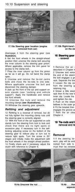
17.10a Steering gear location (engine<br />
removed from car)<br />
disengage it from the steering gear (see<br />
illustration).<br />
6 Set the front wheels in the straight-ahead<br />
position then unscrew the clamp bolt securing<br />
the inner column to the steering gear pinion.<br />
Where applicable, remove the trim panel for<br />
access to the clamp bolt.<br />
7 Prise the inner column up from the pinion<br />
as far as it will go. Do not bend the clamp<br />
open.<br />
8 Unscrew and remove the tie-rod centre<br />
bolts and move the tie-rods to one side.<br />
Where applicable unscrew the bolt and<br />
disconnect the steering damper.<br />
9 Jack up the front of the car and support on<br />
axle stands (see “Jacking and vehicle<br />
support"). Apply the handbrake and remove<br />
the front wheels.<br />
10 Unscrew the nuts and remove the<br />
mounting clamps (see illustrations).<br />
11 Withdraw the steering gear upwards.<br />
Refitting and adjustment<br />
12 Refitting is a reversal of removal, but do<br />
not fully tighten the mounting clamp nuts until<br />
the steering gear is correctly aligned.<br />
13 With the front of the car supported on axle<br />
stands turn the steering from lock to lock and<br />
check that there are no tight spots or<br />
excessive play. If necessary turn in the selflocking<br />
adjusting screw on the bottom of the<br />
steering gear to reduce play or turn out to<br />
reduce tight spots. Turn the screw in 20°<br />
stages and initially make the adjustment with<br />
the front wheels in the straight ahead position.<br />
14 Finally check and if necessary adjust the<br />
clutch with reference to Chapter 6.<br />
17.10b Right-hand side mounting clamp<br />
on the steering gear<br />
1 Remove the air cleaner and duct as<br />
described in Chapter 4.<br />
2 Unscrew and remove the clamp bolt from<br />
the end of the steering gear rack. Note that<br />
the bolt engages a groove on the side of the<br />
rack. Separate the bracket from the rack.<br />
3 Loosen the clip and withdraw the bellows<br />
from the steering gear together with the<br />
retaining ring.<br />
4 Smear a little steering gear grease on the<br />
rack then fit the new bellows together with the<br />
inner clip. Locate the bellows on the housing<br />
and tighten the clip.<br />
5 Push on the retaining ring and locate the<br />
bellows in the outer groove.<br />
6 Fit the bracket then insert the bolt so that it<br />
engages the groove and tighten the nut.<br />
7 Refit the air cleaner with reference to<br />
Chapter 4.<br />
Removal<br />
1 If the steering tie-rod and balljoints are<br />
worn, play will be evident as the roadwheel is<br />
rocked from side to side, and the balljoint<br />
must then be renewed. On RHD models the<br />
lg.2 Steering tie-rod centre bolts<br />
left-hand tie-rod is adjustable and the balljoint<br />
on this tie-rod can be renewed separately,<br />
however the right-hand tie-rod must be<br />
renewed complete. On LHD models the tierods<br />
are vice versa.<br />
2 If the complete tie-rod is to be removed<br />
unscrew the centre bolt preferably with the<br />
weight of the car on the wheels otherwise the<br />
rubber bush may be damaged (see<br />
illustration).<br />
3 Jack up the front of the car and support on<br />
axle stands (see “Jacking and vehicle<br />
support”). Apply the handbrake and remove<br />
the front wheel(s).<br />
4 Unscrew the balljoint nut then use a<br />
balljoint separator tool to release the joint<br />
from the strut (see illustrations).<br />
5 Withdraw the tie-rod or, if removing only the<br />
tie-rod end, loosen the locknut and unscrew<br />
the tie-rod end.<br />
Refitting<br />
6 Refitting is a reversal of removal, but tighten<br />
the nuts to the specified torque and check the<br />
front wheel alignment (refer to Section 20).<br />
Definitions<br />
1 A car’s steering and suspension geometry<br />
is defined in four basic settings - all angles are<br />
expressed in degrees (toe settings are also<br />
expressed as a measurement); the steering<br />
19.4a Unscrew the nut . . . 19.4b . . . then use a balljoint<br />
separator tool . . .<br />
19.4c . . . to release the tie-rod


