

Contents - Volkspage
Contents - Volkspage
Contents - Volkspage

Create successful ePaper yourself
Turn your PDF publications into a flip-book with our unique Google optimized e-Paper software.
Driveshafts 8.3<br />
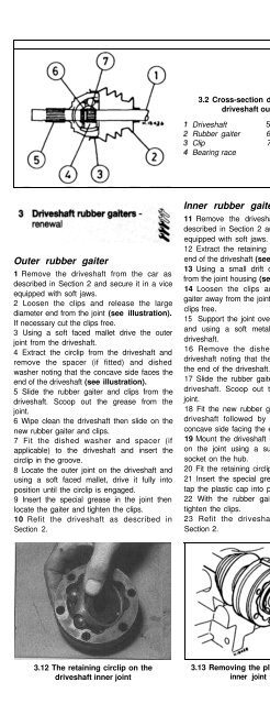
3.2 Cross-section diagram of the<br />
driveshaft outer joint<br />
Driveshaft<br />
Rubber gaiter<br />
Clip<br />
Bearing race<br />
5 Splined shaft<br />
6 Distance washer<br />
7 Dished washer<br />
Outer rubber gaiter<br />
1 Remove the driveshaft from the car as<br />
described in Section 2 and secure it in a vice<br />
equipped with soft jaws.<br />
2 Loosen the clips and release the large<br />
diameter end from the joint (see illustration).<br />
If necessary cut the clips free.<br />
3 Using a soft faced mallet drive the outer<br />
joint from the driveshaft.<br />
4 Extract the circlip from the driveshaft and<br />
remove the spacer (if fitted) and dished<br />
washer noting that the concave side faces the<br />
end of the driveshaft (see illustration).<br />
5 Slide the rubber gaiter and clips from the<br />
driveshaft. Scoop out the grease from the<br />
joint.<br />
6 Wipe clean the driveshaft then slide on the<br />
new rubber gaiter and clips.<br />
7 Fit the dished washer and spacer (if<br />
applicable) to the driveshaft and insert the<br />
circlip in the groove.<br />
8 Locate the outer joint on the driveshaft and<br />
using a soft faced mallet, drive it fully into<br />
position until the circlip is engaged.<br />
9 Insert the special grease in the joint then<br />
locate the gaiter and tighten the clips.<br />
10 Refit the driveshaft as described in<br />
Section 2.<br />
Inner rubber gaiter<br />
11 Remove the driveshaft from the car as<br />
described in Section 2 and secure it in a vice<br />
equipped with soft jaws.<br />
12 Extract the retaining circlip from the inner<br />
end of the driveshaft (see illustration).<br />
13 Using a small drift drive the plastic cap<br />
from the joint housing (see illustration).<br />
14 Loosen the clips and slide the rubber<br />
gaiter away from the joint. If necessary cut the<br />
clips free.<br />
15 Support the joint over the jaws of the vice<br />
and using a soft metal drift, drive out the<br />
driveshaft.<br />
16 Remove the dished washer from the<br />
driveshaft noting that the concave side faces<br />
the end of the driveshaft.<br />
17 Slide the rubber gaiter and clips from the<br />
driveshaft. Scoop out the grease from the<br />
joint.<br />
18 Fit the new rubber gaiter and clips to the<br />
driveshaft followed by the dished washer,<br />
concave side facing the end of the driveshaft.<br />
19 Mount the driveshaft in the vice then drive<br />
on the joint using a suitable metal tube or<br />
socket on the hub.<br />
20 Fit the retaining circlip in its groove.<br />
21 Insert the special grease in the joint then<br />
tap the plastic cap into position.<br />
22 With the rubber gaiter correctly located,<br />
tighten the clips.<br />
23 Refit the driveshaft as described in<br />
Section 2.<br />
Checking<br />
1 If any of the checks described in Chapter 1<br />
reveal wear in any driveshaft joint, first remove<br />
the roadwheel trims and check that the<br />
driveshaft retaining nuts are tight.<br />
2 Road test the vehicle, and listen for a metallic<br />
clicking from the front as the vehicle is driven<br />
slowly in a circle on full lock. If evident, this<br />
indicates wear in the outer constant velocity<br />
joint(s). This means that the joint(s) must be<br />
renewed; reconditioning is not possible.<br />
3 If vibration, consistent with road speed, is<br />
felt through the car when accelerating, there is<br />
a possibility of wear in the inner constant<br />
velocity joint(s).<br />
4 The procedure for removing or renewing<br />
the joints is described in Section 3, however if<br />
necessary the joints may be dismantled as<br />
follows for examination or for cleaning where<br />
the gaiters have broken and the joints have<br />
been contaminated with dirt or water.<br />
Cleaning<br />
Outer joint<br />
5 With the joint removed as described in<br />
Section 3, mark the hub in relation to the cage<br />
and joint housing.<br />
6 Swivel the hub and cage and remove the<br />
balls one at a time.<br />
3.12 The retaining circlip on the 3.13 Removing the plastic cap from the<br />
driveshaft inner joint<br />
inner joint housing<br />
4.7 Removing the cage and hub from the<br />
outer joint housing<br />
Arrow shows rectangular aperture


