

Contents - Volkspage
Contents - Volkspage
Contents - Volkspage

You also want an ePaper? Increase the reach of your titles
YUMPU automatically turns print PDFs into web optimized ePapers that Google loves.
4A.6 Fuel system: single-point injection models<br />
6.5 Slacken the hose clips and disconnect<br />
the fuel lines from either side of the filter<br />
Lift pump and<br />
fuel gauge sender assembly<br />
Removal<br />
3 It is advisable to carry out this operation<br />
when the fuel tank is almost empty.<br />
4 Refer to Section 9 and depressurise the fuel<br />
system.<br />
5 Ensure that the vehicle is parked on a level<br />
surface, then disconnect the battery negative<br />
cable and position it away from the terminal.<br />
6 Refer to Chapter 11 and pivot the rear seat<br />
cushion upwards and forwards.<br />
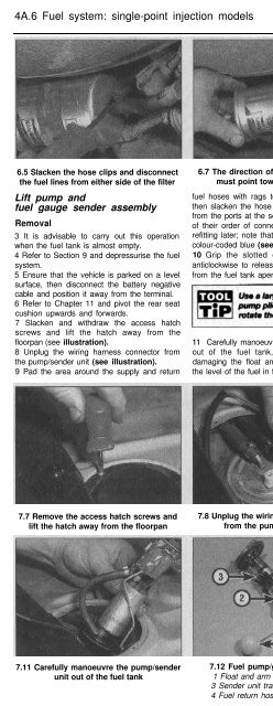
7 Slacken and withdraw the access hatch<br />
screws and lift the hatch away from the<br />
floorpan (see illustration).<br />
8 Unplug the wiring harness connector from<br />
the pump/sender unit (see illustration).<br />
9 Pad the area around the supply and return<br />
6.7 The direction of flow arrow marking<br />
must point towards the engine<br />
fuel hoses with rags to absorb any split fuel,<br />
then slacken the hose clips and remove them<br />
from the ports at the sender unit. Make a note<br />
of their order of connection to ensure correct<br />
refitting later; note that the fuel return hose is<br />
colour-coded blue (see illustration).<br />
10 Grip the slotted outer ring and turn it<br />
anticlockwise to release the pump/sender unit<br />
from the fuel tank aperture.<br />
11 Carefully manoeuvre the pump/sender unit<br />
out of the fuel tank, taking care to avoid<br />
damaging the float arm. Hold the unit above<br />
the level of the fuel in the tank until the excess<br />
fuel has drained out (see illustration). Recover<br />
the rubber seal.<br />
12 Remove the lift pump/sender unit from the<br />
vehicle and lay it on an absorbent card or rag,<br />
in a well ventilated area (see illustration).<br />
Inspect the float at the end of the sender unit<br />
arm for punctures and fuel ingress - renew the<br />
unit if it appears damaged.<br />
13 Inspect the sender unit wiper and track:<br />
carefully clean off any dirt and debris that may<br />
have accumulated and look for breaks or<br />
corrosion on the track windings.<br />
14 Inspect the rubber seal from the fuel tank<br />
aperture for signs of fatigue - renew it if<br />
necessary (see illustration).<br />
Refitting<br />
15 Refit the sender unit by following the<br />
removal procedure in reverse, noting the<br />
following points:<br />
a) Smear the tank aperture rubber seal with<br />
clean fuel before fitting it in position.<br />
b) Reconnect the fuel supply and return<br />
hoses according to the notes made<br />
during removal.<br />
Line fuel pump<br />
Removal<br />
16 The line fuel pump is mounted alongside<br />
the fuel accumulator, behind the fuel tank, at<br />
7.7 Remove the access hatch screws and<br />
lift the hatch away from the floorpan<br />
7.8 Unplug the wiring harness connector<br />
from the pump/sender unit<br />
7.9 Fuel pump connections<br />
1 Supply hose 2 Return hose<br />
7.11 Carefully manoeuvre the pump/sender<br />
unit out of the fuel tank<br />
7.12 Fuel pump/gauge sender unit<br />
1 Float and arm 2 Fuel pump<br />
3 Sender unit track and wiper<br />
4 Fuel return hose<br />
7.14 Inspect the rubber seal from the<br />
fuel tank aperture for signs of fatigue -<br />
renew it if necessary


