

Contents - Volkspage
Contents - Volkspage
Contents - Volkspage

Create successful ePaper yourself
Turn your PDF publications into a flip-book with our unique Google optimized e-Paper software.
Suspension and steering 10.3<br />
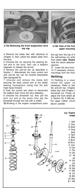
2.10a Removing the front suspension strut<br />
top cap<br />
2.10b View of the front suspension strut<br />
upper mounting from below<br />
4 Remove the brake disc with reference to<br />
Chapter 9, then unbolt the splash plate from<br />
the strut.<br />
5 Unscrew the nut securing the steering tierod<br />
end to the strut, then use a balljoint<br />
separator to release the tie-rod.<br />
6 Remove the anti-roll bar as described in<br />
Section 7. Alternatively the track control arm<br />
and anti-roll bar can be levered downwards<br />
later (paragraph 8).<br />
7 Unscrew and remove the clamp bolt<br />
securing the track control arm to the wheel<br />
bearing housing/strut noting that the bolt<br />
head faces forward.<br />
8 Push the control arm down to disconnect<br />
the balljoint then move the strut sideways.<br />
9 Unscrew the driveshaft nut, then pull the<br />
strut out and at the same time tap the<br />
driveshaft through the hub with a mallet.<br />
the cap from the top of the strut then unscrew<br />
the self-locking nut while supporting the strut<br />
from below (see illustrations). If necessary<br />
hold the shock absorber rod stationary with a<br />
spanner.<br />
11 Lower the strut from under the car.<br />
12 If necessary remove the cups and rubber<br />
mountings from the front suspension tower.<br />
Refitting<br />
10 Working in the engine compartment prise talcum powder.<br />
13 Refitting is a reversal of removal, but<br />
renew the upper rubber mountings if<br />
necessary. Refer to Section 7 when refitting<br />
the anti-roll bar, Chapter 9 when refitting the<br />
brake disc and Chapter 8 when tightening the<br />
driveshaft nut. Finally check and if necessary<br />
adjust the front wheel alignment as described<br />
in Section 20. If difficulty is experienced fitting<br />
the upper rubber mounting first dust it with<br />
Exploded view of front<br />
suspension strut<br />
1 Self-locking nut<br />
2 Damping ring<br />
3 Slotted nut<br />
4 Suspension strut<br />
bearing<br />
5 Spring retainer<br />
6 Washer<br />
7 Bump stop<br />
8 Boot<br />
9 Coil spring<br />
10 Screw cap<br />
11 Piston rod guide seal<br />
12 Shock absorber<br />
13 ‘Wet type’shock<br />
absorber<br />
14 Shock absorber<br />
cartridge<br />
15 Wheel bearing housing<br />
16 Splash plate<br />
17 Wheel bearing<br />
18 Circlip<br />
19 Wheel hub<br />
20 Brake disc<br />
2 1 Wheel bolt<br />
A! Warning: Before attempting to<br />
dismantle the suspension strut,<br />
a suitable tool to hold the coil<br />
spring in compression must be<br />
obtained. Adjustable coil spring<br />
compressors are readily available, and are<br />
recommended for this operation. Any<br />
attempt to dismantle the strut without<br />
such a tool is likely to result in damage or<br />
personal injuy.<br />
Note: A special slotted socket is required to<br />
remove and refit the upper spring seat<br />
retaining nut; alternatives to the VW tool are<br />
available from specialist automotive tool<br />
manufacturers (eg. Sykes Pickavant) (see Tool<br />
Tip).<br />
Removal<br />
1 Remove the front suspension strut as<br />
described in Section 2.<br />
2 Using a spring compression tool compress<br />
the coil spring until it is clear of the upper<br />
retainer.<br />
3 Using the special slotted socket, unscrew<br />
the slotted nut from the shock absorber rod<br />
and withdraw the spring retainer, washer,<br />
bump stop, boot, and coil spring (see<br />
illustration). If a special tool to engage the<br />
slotted nut is not available, use a pair of grips.<br />
4 Remove the compressor tool. 10<br />
Refitting<br />
5 Refitting is a reversal of removal with<br />
reference to Section 2 when refitting the strut.<br />
Tighten the slotted nut to the specified torque.


