

Contents - Volkspage
Contents - Volkspage
Contents - Volkspage

You also want an ePaper? Increase the reach of your titles
YUMPU automatically turns print PDFs into web optimized ePapers that Google loves.
Ignition systems 5B.3<br />
9 Disconnect the LT cable from the ignition<br />
coil at the multiway connector (refer to<br />
illustration 3.8).<br />
10 Slacken and withdraw the mounting<br />
screws, remove the brackets and detach the<br />
earthing strap (where applicable). Remove the<br />
ignition coil from the engine bay.<br />
Refitting<br />
11 Refitting is a reversal of removal.<br />
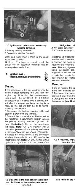
3.3 Ignition coil primary and secondary<br />
winding terminals<br />
A Primary winding terminals<br />
B Secondary winding terminals<br />
check and renew them if there is any doubt<br />
about their condition.<br />
14 If no HT voltage is present, check the<br />
ignition coil; its secondary windings may be<br />
breaking down under load.<br />
Testing<br />
1 The resistance of the coil windings may be<br />
tested without removing the unit from the<br />
engine bay. Note that the measurements<br />
taken will be affected by ambient<br />
temperature, so it is good idea to conduct this<br />
test after the engine has been running for a<br />
while, as the coil will then be at its normal<br />
operating temperature.<br />
2 Disconnect the battery negative cable and<br />
position it away from the terminal.<br />
3 Connect the probes of a multimeter set to<br />
the resistance measurement function across<br />
the primary winding terminals (1 and 15)<br />
(see illustration). Record the resistance<br />
indicated. Note: On G40 mode/s with a<br />
cylindrical ignition coil, the primary resistance<br />
is measured between the ‘+’ and ´-’ terminals.<br />
4 Repeat the measurement at the secondary<br />
winding terminals (4 and 15) (refer to<br />
illustration 3.3). Note: On G40 models with a<br />
cylindrical ignition coil, the secondary<br />
3.8 Ignition coil connectors<br />
A HT cable connector<br />
B LT cable multiway connector<br />
Removal<br />
resistance is measured between the HT lead 1 Disconnect the battery negative cable and<br />
terminal and ‘-’ terminal.<br />
position it away from the terminal.<br />
5 Compare the measurements with the Specifications<br />
and renew the coil if necessary. referring to of Chapter 2A for guidance.<br />
2 Set the engine to TDC on cylinder No 1,<br />
Note: This test pinpoints short or open circuits 3 If required, unplug all five HT leads from the<br />
within the ignition coil, but does not a/low distributor cap - label them to aid refitting later<br />
diagnosis of failures that occur whilst the coil (see illustration).<br />
is under load. Under these circumstances, the 4 Unplug the screening cap earth strap from<br />
coil should be tested by an automotive the distributor body (see illustration).<br />
electrical specialist.<br />
5 Unplug the Hall sensor cable from the<br />
distributor body at the connector (see<br />
Removal<br />
illustration).<br />
6 On all models, the ignition coil is mounted 6 Remove the screws or prise off the<br />
at the front left hand corner of the engine bay. retaining clips (as applicable), then lift off the<br />
7 Disconnect the battery negative cable and distributor cap. Check at this point that the<br />
position it away from the terminal.<br />
centre of the rotor arm electrode is aligned<br />
8 Unplug the HT lead from the ignition coil at with the cylinder No 1 marking on the<br />
the connector (see illustration).<br />
distributor body (see illustrations).<br />
4.3 If required, unplug all five HT leads<br />
from the distributor cap<br />
4.4 Unplug the screening cap earth strap<br />
from the distributor body<br />
4.5 Disconnect the Hall sender cable from<br />
the distributor at the multiway connector<br />
(arrowed)<br />
4.6a Prise off the retaining clips . . . 4.6b . . . then lift off the distributor cap


