

Contents - Volkspage
Contents - Volkspage
Contents - Volkspage

Create successful ePaper yourself
Turn your PDF publications into a flip-book with our unique Google optimized e-Paper software.
2B.4 Engine removal and overhaul procedures<br />
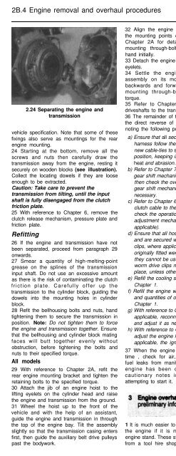
2.24 Separating the engine and<br />
transmission<br />
vehicle specification. Note that some of these<br />
fixings also serve as mountings for the rear<br />
engine mounting.<br />
24 Starting at the bottom, remove all the<br />
screws and nuts then carefully draw the<br />
transmission away from the engine, resting it<br />
securely on wooden blocks (see illustration).<br />
Collect the locating dowels if they are loose<br />
enough to be extracted.<br />
Caution: Take care to prevent the<br />
transmission from tilting, until the input<br />
shaft is fully disengaged from the clutch<br />
friction plate.<br />
25 With reference to Chapter 6, remove the<br />
clutch release mechanism, pressure plate and<br />
friction plate.<br />
Refitting<br />
26 If the engine and transmission have not<br />
been separated, proceed from paragraph 29<br />
onwards.<br />
27 Smear a quantity of high-melting-point<br />
grease on the splines of the transmission<br />
input shaft. Do not use an excessive amount<br />
as there is the risk of contaminating the clutch<br />
friction plate. Carefully offer up the<br />
transmission to the cylinder block, guiding the<br />
dowels into the mounting holes in cylinder<br />
block.<br />
28 Refit the bellhousing bolts and nuts, hand<br />
tightening them to secure the transmission in<br />
position. Note: Do not tighten them to force<br />
the engine and transmission together. Ensure<br />
that the bellhousing and cylinder block mating<br />
faces will butt together evenly without<br />
obstruction, before tightening the bolts and<br />
nuts to their specified torque.<br />
All models<br />
29 With reference to Chapter 2A, refit the<br />
rear engine mounting bracket and tighten the<br />
retaining bolts to the specified torque.<br />
30 Attach the jib of an engine hoist to the<br />
lifting eyelets on the cylinder head and raise<br />
the engine and transmission from the ground.<br />
31 Wheel the hoist up to the front of the<br />
vehicle and with the help of an assistant,<br />
guide the engine and transmission in through<br />
the top of the engine bay. Tilt the assembly<br />
slightly so that the transmission casing enters<br />
first, then guide the auxiliary belt drive pulleys<br />
past the bodywork.<br />
32 Align the engine mounting brackets with<br />
the mounting points on the body - refer to<br />
Chapter 2A for details. Insert the engine<br />
mounting through-bolts, tightening them by<br />
hand initially.<br />
33 Detach the engine hoist jib from the lifting<br />
eyelets.<br />
34 Settle the engine and transmission<br />
assembly on its mountings by rocking it<br />
backwards and forwards, then tighten the<br />
mounting through-bolts to the specified<br />
torque.<br />
35 Refer to Chapter 8 and reconnect the<br />
driveshafts to the transmission.<br />
36 The remainder of the refitting sequence is<br />
the direct reverse of the removal procedure,<br />
noting the following points:<br />
a) Ensure that all sections of the wiring<br />
harness follow their original routing; use<br />
new cable-ties to secure the harness in<br />
position, keeping it away from sources of<br />
heat and abrasion.<br />
b) Refer to Chapter 7 and reconnect the<br />
gear shift mechanism to the transmission,<br />
then check the overall operation of the<br />
gear shift mechanism, adjusting it if<br />
necessary.<br />
c) Refer to Chapter 6 and reconnect the<br />
clutch cable to the transmission, then<br />
check the operation of the automatic<br />
adjustment mechanism (where<br />
applicable).<br />
d) Ensure that all hoses are correctly routed<br />
and are secured with the correct hose<br />
clips, where applicable. If the hose clips<br />
originally fitted were of the crimp variety,<br />
they cannot be used again; proprietary<br />
worm drive clips must be fitted in their<br />
place, unless otherwise specified.<br />
e) Refill the cooling system as described in<br />
Chapter 1.<br />
f) Refill the engine with appropriate grades<br />
and quantities of oil, as detailed in<br />
Chapter 1.<br />
g) With reference to Chapter 4A or B as<br />
applicable, reconnect the throttle cable<br />
and adjust it as necessary.<br />
h) With reference to Chapter 5B, check and<br />
adjust the engine idle speed and where<br />
applicable, the ignition timing.<br />
37 When the engine is stat-ted for the first<br />
time , check for air, coolant, lubricant and<br />
fuel leaks from manifolds, hoses etc. If the<br />
engine has been overhauled, read the<br />
cautionary notes in Section 13 before<br />
attempting to start it.<br />
1 It is much easier to dismantle and work on<br />
the engine if it is mounted on a portable<br />
engine stand. These stands can often be hired<br />
from a tool hire shop. Before the engine is<br />
mounted on a stand, the flywheel should be<br />
removed, so that the stand bolts can be<br />
tightened into the end of the cylinder block/<br />
crankcase.<br />
2 If a stand is not available, it is possible to<br />
dismantle the engine with it blocked up on a<br />
sturdy workbench, or on the floor. Be very<br />
careful not to tip or drop the engine when<br />
working without a stand.<br />
3 If you intend to obtain a reconditioned<br />
engine, all ancillaries must be removed first, to<br />
be transferred to the replacement engine (just<br />
as they will if you are doing a complete engine<br />
overhaul yourself). These components include<br />
the following:<br />
a) Alternator (including mounting brackets)<br />
and starter motor (Chapter 5A).<br />
b) The ignition system and HT components<br />
including all sensors, distributor, HT leads<br />
and spark plugs (Chapters 1 and 5).<br />
c) The fuel injection system components<br />
(Chapter 4 Parts A and B)<br />
d) All electrical switches, actuators and<br />
sensors, and the engine wiring harness<br />
(Chapter 4 Parts A and B, Chapter 5B).<br />
e) inlet and exhaust manifolds (Chapter 2A).<br />
f) The engine oil level dipstick (Chapter 1)<br />
g) Engine mountings (Chapter 2A and B).<br />
h) Flywheel (Chapter 28)<br />
i) Clutch components (Chapter 6)<br />
Note: When removing the external<br />
components from the engine, pay close<br />
attention to details that may be helpful or<br />
important during refitting. Note the fitted<br />
position of gaskets, seals, spacers, pins,<br />
washers, bolts, and other small components.<br />
4 If you are obtaining a “short” engine (which<br />
consists of the engine cylinder block/<br />
crankcase, crankshaft, pistons and<br />
connecting rods, all fully assembled), then the<br />
cylinder head, sump and baffle plate, oil<br />
pump, timing belt (together with its tensioner<br />
and covers), auxiliary belt (together with its<br />
tensioner), coolant pump, thermostat housing,<br />
coolant outlet elbows, oil filter housing and<br />
where applicable oil cooler will also have to be<br />
removed.<br />
5 If you are planning a complete overhaul, the<br />
engine can be dismantled in the order given<br />
below:<br />
a) Inlet and exhaust manifolds.<br />
b) Timing be/t, sprockets and tensioner.<br />
c) Cylinder head.<br />
d) Flywheel driveplate.<br />
e) Sump.<br />
f) Oil pump.<br />
g) Piston/connecting rod assemblies.<br />
h) Crankshaft.<br />
6 Before beginning the dismantling and<br />
overhaul procedures, make sure that you have<br />
all of the tools necessary. Refer to “Tools and<br />
working facilities” in the Reference Section of<br />
this manual for further information.


