

Contents - Volkspage
Contents - Volkspage
Contents - Volkspage

Create successful ePaper yourself
Turn your PDF publications into a flip-book with our unique Google optimized e-Paper software.
Fuel system: single-point injection models 4A.3<br />
illustration 2.3) and remove the temperature<br />
regulator from the air cleaner housing.<br />
Recover the gasket.<br />
Refitting<br />
4 Refit the regulator by following the removal<br />
procedure in reverse. Use a new gasket.<br />
Removal<br />
1 Remove the throttle body air box/air cleaner<br />
as described in Section 2.<br />
2 At the throttle body, disconnect the<br />
accelerator cable inner from the throttle valve<br />
spindle plate (see illustration).<br />
3 Remove the adjustment clip and extract the<br />
cable outer from the mounting bracket (refer<br />
to illustration 4.2).<br />
4 To improve access, refer to Chapter 11 and<br />
8<br />
9<br />
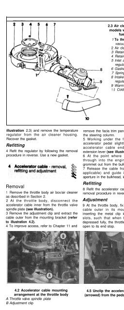
2.3 Air cleaner assembly -<br />
models with single-point<br />
fuel injection<br />
1 To throttle body<br />
vacuum tapping<br />
2 Air cleaner housing<br />
3 Retaining ring<br />
4 Retaining nut<br />
5 Inlet air temperature<br />
regulator valve<br />
6 Gasket<br />
7 Spring clip<br />
8 Intake air temperature<br />
regulating flap<br />
9 Warm air ducting<br />
1 0 Cold air ducting<br />
remove the facia trim panels from underneath<br />
the steering column.<br />
5 Working under the facia, depress the<br />
accelerator pedal slightly, then unclip the<br />
accelerator cable end from the pedal<br />
extension lever (see illustration).<br />
6 At the point where the cable passes<br />
through into the engine bay, prise the<br />
grommet out from the bulkhead.<br />
7 Release the cable from its clips (where<br />
applicable) and guide it out through the<br />
aperture in the bulkhead, into the engine bay.<br />
Refitting<br />
8 Refit the accelerator cable by following the<br />
removal procedure in reverse.<br />
Adjustment<br />
9 At the throttle body, fix the position of the<br />
cable outer in its mounting bracket by<br />
inserting the metal clip in one the locating<br />
slots, such that when the accelerator is<br />
depressed fully, the throttle valve is held wide<br />
open to its end stop.<br />
5 Fuel injection system<br />
components -<br />
removal and refitting<br />
A<br />
Warning:<br />
!<br />
Throttle body<br />
Removal<br />
Observe the<br />
precautions in Section 1 before<br />
working on any component in<br />
the fuel system.<br />
1 Refer to Section 2 and remove the air<br />
cleaner/throttle body air box.<br />
2 Refer to Section 9 and depressurise the fuel<br />
system, then disconnect the battery negative<br />
cable and position it away from the terminal.<br />
3 Disconnect the fuel supply and return<br />
hoses from the ports on the side of the throttle<br />
body. Note the arrows that denote the<br />
direction of fuel flow, and mark the hoses<br />
accordingly (see illustration).<br />
4 Unplug the wiring harness from the throttle<br />
body at the connectors, labelling them to aid<br />
correct refitting later. Similarly, disconnect all<br />
vacuum hoses from the throttle body and<br />
label them carefully; it is essential that the<br />
hoses are reconnected to the correct vacuum<br />
ports on reassembly.<br />
5 Refer to Section 4 and disconnect the<br />
accelerator cable from the throttle body.<br />
6 Remove the through-bolts and lift the upper<br />
and lower sections of the throttle body away<br />
from the inlet manifold.<br />
7 The lower section of the throttle body may be<br />
separated from the upper section by releasing<br />
the clips. If required, the inter-mediate flange<br />
may be detached from the inlet manifold by<br />
removing the nuts from the four through-bolts.<br />
Refitting<br />
8 Refitting is a reversal of removal; renew all<br />
gaskets where appropriate. Finally, check and<br />
if necessary adjust the accelerator cable.<br />
Fuel injector<br />
Removal<br />
9 Refer to Section 2 and remove the air<br />
cleaner housing.<br />
4A<br />
4.2 Accelerator cable mounting<br />
arrangement at the throttle body<br />
A Throttle valve spindle plate<br />
B Adjustment clip<br />
4.5 Unclip the accelerator cable inner<br />
(arrowed) from the pedal extension lever<br />
5.3 Throttle body fuel supply and return<br />
hoses and ports


