

Contents - Volkspage
Contents - Volkspage
Contents - Volkspage

You also want an ePaper? Increase the reach of your titles
YUMPU automatically turns print PDFs into web optimized ePapers that Google loves.
Fuel system: multi-point injection models 4B.3<br />
2.2 Detach the cold inlet air ducting from<br />
the cowling above the radiator<br />
shield on the exhaust manifold (see illustration)<br />
4 Remove the four retaining nuts, then lift the<br />
air cleaner out of the engine bay and recover<br />
the rubber mountings (see illustration). To<br />
improve access, detach the charcoal canister<br />
vacuum hoses, but make a careful note of the<br />
order of fitting to ensure correct refitting.<br />
Refitting<br />
5 Refit the air cleaner by following the<br />
removal procedure in reverse.<br />
General information<br />
1 The inlet air regulation system consists of a<br />
temperature controlled vacuum switch,<br />
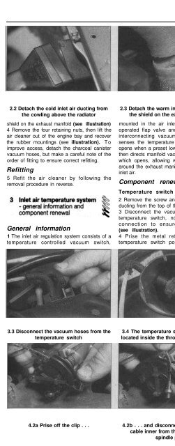
3.3 Disconnect the vacuum hoses from the<br />
temperature switch<br />
2.3 Detach the warm inlet air ducting from<br />
the shield on the exhaust manifold<br />
mounted in the air inlet ducting, a vacuum<br />
operated flap valve and several lengths of<br />
interconnecting vacuum hose. The switch<br />
senses the temperature of the inlet air and<br />
opens when a preset lower limit is reached. It<br />
then directs manifold vacuum to the flap valve<br />
which opens, allowing warm air drawn from<br />
around the exhaust manifold to blend with the<br />
inlet air.<br />
Component renewal<br />
Temperature switch<br />
2 Remove the screw and detach the inlet air<br />
ducting from the top of the throttle body.<br />
3 Disconnect the vacuum hoses from the<br />
temperature switch, noting their order of<br />
connection to ensure correct refitting<br />
(see illustration).<br />
4 Prise the metal retaining clip off the<br />
temperature switch ports, then press the<br />
3.4 The temperature switch (arrowed) is<br />
located inside the throttle body inlet duct<br />
2.4 Remove the four air cleaner<br />
retaining nuts (arrowed)<br />
switch body inside the ducting. Recover the<br />
gaskets (see illustration).<br />
5 Refitting is a reversal of removal.<br />
Flap valve<br />
6 The flap valve is removed with the air<br />
cleaner inlet ducting - remove the screw and<br />
detach the ducting from the front of the air<br />
cleaner.<br />
A<br />
Warning:<br />
!<br />
Removal<br />
Observe the<br />
precautions in Section 1 before<br />
working on any component in<br />
the fuel system.<br />
1 Remove the ducting from the top of the<br />
throttle body, as described in Section 5, to<br />
improve access.<br />
2 Prise off the clip and disconnect the<br />
accelerator cable inner from the throttle valve<br />
spindle plate (see illustrations).<br />
3 Remove the metal clip and extract the<br />
cable outer from the mounting bracket (see<br />
illustration).<br />
4 Refer to Chapter 11 and remove the facia<br />
trim panels from underneath the steering<br />
column.<br />
5 Depress the accelerator pedal slightly, then<br />
unclip the accelerator cable end from the<br />
pedal extension lever.<br />
6 At the point where the cable passes<br />
4.2a Prise off the clip . . . 4.2b . . . and disconnect the accelerator<br />
cable inner from the throttle valve<br />
spindle plate<br />
4.3 Remove the metal clip and extract the<br />
cable outer from the mounting bracket


