- Page 2:
Introduction to Fire Safety Managem
- Page 6:
Introduction to Fire Safety Managem
- Page 10:
Contents PREFACE ix ACKNOWLEDGEMENT
- Page 14:
Contents 9.4 Building construction
- Page 18:
Preface Introduction to Fire Safety
- Page 22:
About the authors Andrew Furness is
- Page 26:
Illustrations credits Figure 5.1 Co
- Page 30:
Illustrations credits Principles of
- Page 34:
Fire safety foundations To enable s
- Page 38:
There can also be signifi cant emot
- Page 42:
REDUNDANCIES REDUCED CASH FLOW INCR
- Page 46:
If a prosecution is brought for a b
- Page 50:
Figure 1.11 Employers are responsib
- Page 54:
Health and safety arrangements Empl
- Page 58:
fi re specifi c issues that the RRF
- Page 62:
Door closer Fire door Keep shut Fig
- Page 66:
Figure 1.19 Stair lift in situation
- Page 70:
So, whom would she sue for her loss
- Page 74:
Once the court has established negl
- Page 78:
Figure 1.25 Powers of enforcement a
- Page 82:
140 120 100 80 60 40 20 0 Figure 1.
- Page 86:
External factors Internal factors A
- Page 90:
the company had fully complied with
- Page 94:
Figure 2.1 ACoP of Management of he
- Page 98:
The organisation element of a safet
- Page 102:
detached building, which included o
- Page 106:
Organising for safety 3.1 Introduct
- Page 110:
Directors and senior managers often
- Page 114:
➤ Ensuring access and egress and
- Page 118:
Table 3.1 A summary of individuals
- Page 122:
and inform employers and other self
- Page 126:
Figure 3.8 Safety representatives h
- Page 130:
➤ To consider enforcing authority
- Page 134:
If a piece of work equipment that i
- Page 138:
4. First aid information 5. Fire fi
- Page 142:
Figure 3.13 Designers have a respon
- Page 146:
3.11 Example NEBOSH questions for C
- Page 150:
Safety culture 4.1 Introduction The
- Page 154:
There are various ‘safety climate
- Page 158:
the culture because if there is dis
- Page 162:
Communication is defi ned as: The i
- Page 166:
emergency medical care and rescue w
- Page 170:
on how much people will remember. A
- Page 174:
Individual factors affecting the sc
- Page 178:
on the culture of an organisation.
- Page 182:
Figure 4.11 Consultation with emplo
- Page 186:
esponsibilities are added such as a
- Page 190:
4.9 Human failure Human beings are
- Page 194:
safety in a way that takes their wh
- Page 198:
Principles of risk assessment 5.1 I
- Page 202:
5.2.6 Risk control systems (RCS) Th
- Page 206:
➤ Safety representatives ➤ Desi
- Page 210:
➤ Location inspection: ➤ Site s
- Page 214:
There are a number of methods for e
- Page 218:
Semi-quantitative analysis The use
- Page 222:
the risk controls, particularly wit
- Page 226:
the hazards that arise from the act
- Page 230:
No. Hazards Persons at risk Risk ra
- Page 234:
General principles of control 6.1 I
- Page 238:
Consultation and the arrangements f
- Page 242:
needs. This assessment must also ta
- Page 246:
High 100% Level of supervision Low
- Page 250:
Table 6.1 Sources of information av
- Page 254:
The documentation should be written
- Page 258:
their condition. Once these often l
- Page 262:
The HSE inspector dealing with the
- Page 266:
OXYGEN Always present in the air Ad
- Page 270:
➤ Boilers, internal combustion en
- Page 274:
capable of producing more vapour th
- Page 278:
unburnt fuel (unburnt products of p
- Page 282:
include basements. On these occasio
- Page 286:
7.5 Explosion As the terminology su
- Page 290:
substance in air may cause an explo
- Page 294:
can be broken down into primary and
- Page 298:
Nozzle Ignition Supressor Pressure
- Page 302:
huge fl ammable gas cloud and that
- Page 306:
Number 25 20 15 10 5 0 Electrical C
- Page 310:
8.1.5 Chemical and LPG (hazardous m
- Page 314:
The selection of incorrect plant an
- Page 318:
Flammable substances Risks arise fr
- Page 322:
Arson also often occurs during tea
- Page 326:
Business operations and activities
- Page 330:
Causes and prevention of fi re Tabl
- Page 334:
Figure 8.16 External tank facility
- Page 338:
Figure 8.19 Example of suitable fl
- Page 342:
Ventilation of storage areas Ventil
- Page 346:
➤ All soft furnishings within the
- Page 350:
LPG powered vehicles are becoming m
- Page 354:
Figure 8.28 Site rules poster The c
- Page 358:
Table 8.4 Electrical safety on cons
- Page 362:
Figure 8.30 Tar boiler used to heat
- Page 366:
Appendix 8.1 Example hot work permi
- Page 370:
Appendix 8.2 Example hot work check
- Page 374:
Fire Protection Causes and preventi
- Page 378:
Backdraught - an explosive reaction
- Page 382:
the design and construction of the
- Page 386:
SC SC Fire door Fire-resisting wall
- Page 390:
Figure 9.9 Class A - complete non-c
- Page 394:
potential to reduce the performance
- Page 398:
Table 9.2 Examples of the marking r
- Page 402:
In many cases services and the hole
- Page 406:
inter -mediate standard but small r
- Page 410:
Evacuation time Evacuation procedur
- Page 414:
total uncontrolled evacuation. Typi
- Page 418:
Table 9.5 Density factors given in
- Page 422:
A x B A - B = Stage 1 B - C = Stage
- Page 426:
stairs 3 Actual Travel Distance Dir
- Page 430:
stairs FIRE WALL space in these are
- Page 434:
A A B 45 (2.5 distance CB) B Figu
- Page 438:
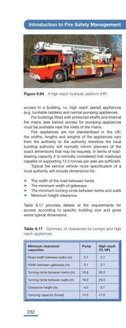
this situation it will be necessary
- Page 442:
Therefore all dead-end corridors th
- Page 446: Number of escape stairs needed is d
- Page 450: Figure 9.46 Metal fi re escape abov
- Page 454: Figure 9.50 Sprinklers that moderat
- Page 458: Table 9.10 Categorisation of emerge
- Page 462: Sign, Colour & Pictogram Descriptio
- Page 466: factors all of which should be iden
- Page 470: are used to prevent accidental disc
- Page 474: Figure 9.66 Typical warning sign to
- Page 478: Control valve Valve spring Discharg
- Page 482: 1.5 m 35m Figure 9.72 Plan drawing
- Page 486: Figure 9.74 Proprietary device for
- Page 490: All such systems, including the ins
- Page 494: during periods of sleep (hotels, ho
- Page 500: Introduction to Fire Safety Managem
- Page 504: Introduction to Fire Safety Managem
- Page 508: Introduction to Fire Safety Managem
- Page 512: 10 Safety The safety of people in t
- Page 516: Introduction to Fire Safety Managem
- Page 520: Introduction to Fire Safety Managem
- Page 524: Introduction to Fire Safety Managem
- Page 528: Introduction to Fire Safety Managem
- Page 532: Introduction to Fire Safety Managem
- Page 536: Introduction to Fire Safety Managem
- Page 540: Introduction to Fire Safety Managem
- Page 544: Introduction to Fire Safety Managem
- Page 548:
Introduction to Fire Safety Managem
- Page 552:
Introduction to Fire Safety Managem
- Page 556:
Introduction to Fire Safety Managem
- Page 560:
Introduction to Fire Safety Managem
- Page 564:
Introduction to Fire Safety Managem
- Page 568:
11 Monitoring, While there is no sp
- Page 572:
Introduction to Fire Safety Managem
- Page 576:
Introduction to Fire Safety Managem
- Page 580:
Introduction to Fire Safety Managem
- Page 584:
Introduction to Fire Safety Managem
- Page 588:
Introduction to Fire Safety Managem
- Page 592:
Introduction to Fire Safety Managem
- Page 596:
Introduction to Fire Safety Managem
- Page 600:
12 Reactive The investigation of fi
- Page 604:
Introduction to Fire Safety Managem
- Page 608:
Introduction to Fire Safety Managem
- Page 612:
Introduction to Fire Safety Managem
- Page 616:
Introduction to Fire Safety Managem
- Page 620:
Introduction to Fire Safety Managem
- Page 624:
Introduction to Fire Safety Managem
- Page 628:
Introduction to Fire Safety Managem
- Page 632:
Introduction to Fire Safety Managem
- Page 636:
Introduction to Fire Safety Managem
- Page 640:
Introduction to Fire Safety Managem
- Page 644:
Introduction to Fire Safety Managem
- Page 648:
Introduction to Fire Safety Managem
- Page 652:
Introduction to Fire Safety Managem
- Page 656:
13 Environmental Fire not only pose
- Page 660:
Introduction to Fire Safety Managem
- Page 664:
Introduction to Fire Safety Managem
- Page 668:
Introduction to Fire Safety Managem
- Page 672:
Introduction to Fire Safety Managem
- Page 676:
Introduction to Fire Safety Managem
- Page 680:
Introduction to Fire Safety Managem
- Page 684:
Introduction to Fire Safety Managem
- Page 688:
14 Fire 14.1 Introduction As has be
- Page 692:
Introduction to Fire Safety Managem
- Page 696:
Introduction to Fire Safety Managem
- Page 700:
Introduction to Fire Safety Managem
- Page 704:
Introduction to Fire Safety Managem
- Page 708:
Introduction to Fire Safety Managem
- Page 712:
Introduction to Fire Safety Managem
- Page 716:
Introduction to Fire Safety Managem
- Page 720:
Introduction to Fire Safety Managem
- Page 724:
Introduction to Fire Safety Managem
- Page 728:
Introduction to Fire Safety Managem
- Page 732:
Introduction to Fire Safety Managem
- Page 736:
Introduction to Fire Safety Managem
- Page 740:
Introduction to Fire Safety Managem
- Page 744:
Introduction to Fire Safety Managem
- Page 748:
Introduction to Fire Safety Managem
- Page 752:
Introduction to Fire Safety Managem
- Page 756:
Introduction to Fire Safety Managem
- Page 760:
Introduction to Fire Safety Managem
- Page 764:
Introduction to Fire Safety Managem
- Page 768:
Introduction to Fire Safety Managem
- Page 772:
Introduction to Fire Safety Managem
- Page 776:
Introduction to Fire Safety Managem
- Page 780:
Introduction to Fire Safety Managem
- Page 784:
Introduction to Fire Safety Managem
- Page 788:
Introduction to Fire Safety Managem
- Page 792:
Introduction to Fire Safety Managem
- Page 796:
Introduction to Fire Safety Managem
- Page 800:
Introduction to Fire Safety Managem
- Page 804:
Introduction to Fire Safety Managem
- Page 808:
Introduction to Fire Safety Managem
- Page 812:
Introduction to Fire Safety Managem
- Page 816:
Introduction to Fire Safety Managem
- Page 820:
Introduction to Fire Safety Managem
- Page 824:
Introduction to Fire Safety Managem
- Page 828:
Introduction to Fire Safety Managem
- Page 832:
Abbreviations AFFF Aqueous Film For
- Page 836:
This page intentionally left blank
- Page 840:
Index BS 5539 Part 1, Monitoring fi
- Page 844:
Index Demolition work, contributes
- Page 848:
Index Fencing, as a security strate
- Page 852:
Index Fire risk assessment process
- Page 856:
Index Hazardous Installation Direct
- Page 860:
Index Montreal Protocol, 221 Motiva
- Page 864:
Index Risk matrix: for determining
- Page 868:
Index SSOW (Safe systems of work),