

TI486 Microprocessor - Al Kossow's Bitsavers
TI486 Microprocessor - Al Kossow's Bitsavers
TI486 Microprocessor - Al Kossow's Bitsavers

Create successful ePaper yourself
Turn your PDF publications into a flip-book with our unique Google optimized e-Paper software.
Overview<br />
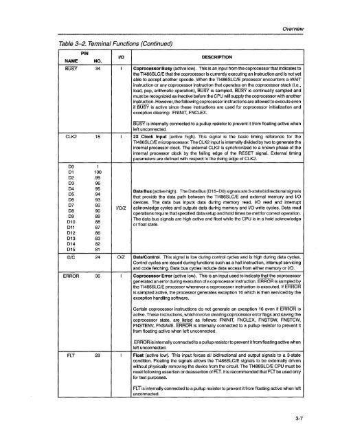
Table 3-2. Terminal Functions (Continued)<br />
NAME<br />
PIN<br />
NO.<br />
1/0 DESCRIPTION<br />
BUSY 34 I Coprocessor Busy (active low). This is an input from the coprocessor that indicates to<br />
the <strong>TI486</strong>SLC/E that the coprocessor is currently executing an instruction and is not yet<br />
able to accept another opcode. When the <strong>TI486</strong>SLC/E processor encounters a WAIT<br />
instruction or any coprocessor instruction that operates on the coprocessor stack (Le.,<br />
load, pop, arithmetic operation), BUSY is sampled. BUSY is continually sampled and<br />
must be recognized as inactive before the CPU will supply the coprocessor with another<br />
instruction. However, the following coprocessor instructions are allowed to execute even<br />
if BUSY is active since these instructions are used for coprocessor initialization and<br />
exception clearing: FNINIT, FNCLEX.<br />
BUSY is internally connected to a pullup resistor to prevent it from floating active when<br />
left unconnected.<br />
CLK2 15 I 2X Clock Input (active high). This signal is the basic timing reference for the<br />
<strong>TI486</strong>SLC/E microprocessor. The CLK2 input is internally divided by two to generate the<br />
internal processor clock. The external CLK2 is synchronized to a known phase of the<br />
internal processor clock by the falling edge of the RESET signal. External timing<br />
parameters are defined with respect to the rising edge of CLK2.<br />
00 1<br />
01 100<br />
02 99<br />
03 96<br />
04 95<br />
05 94<br />
06 93<br />
07 92<br />
08 90<br />
09 89<br />
010 88<br />
011 87<br />
012 86<br />
013 83<br />
014 82<br />
015 81<br />
I/OIZ<br />
Data Bus (active high). The Oata Bus (015-00) signals are 3-state bidirectional signals<br />
that provide the data path between the <strong>TI486</strong>SLC/E and external memory and 1/0<br />
devices. The data bus inputs data during memory read, 1/0 read and interrupt<br />
acknowledge cycles and outputs data during memory and 1/0 write cycles. Oata read<br />
operations require that specified data setup and hold times be met for correct operation.<br />
The data bus signals are high active and float while the CPU is in a hold acknowledge<br />
or float state.<br />
O/C 24 OIZ Data/Control. This signal is low during control cycles and is high during data cycles.<br />
Control cycles are issued during functions such as a halt instruction, interrupt servicing<br />
and code fetching. Oata bus cycles include data access from either memory or 1/0.<br />
ERROR 36 I Coprocessor Error (active low). This is an input used to indicate that the coprocessor<br />
generated an error during execution of a coprocessor instruction. ERROR is sampled by<br />
the <strong>TI486</strong>SLC/E processor whenever a coprocessor instruction is executed. If ERROR<br />
is sampled active, the processor generates exception 16 which is then serviced by the<br />
exception handling software.<br />
Certain coprocessor instructions do not generate an exception 16 even if ERROR is<br />
active. These instructions, which involve clearing coprocessor error flags and saving the<br />
coprocessor state, are listed as follows: FNINIT, FNCLEX, FNSTSW, FNSTCW,<br />
FNSTENV, FNSAVE. ERROR is internally connected to a pullup resistor to prevent it<br />
from floating active when left unconnected.<br />
ERROR is internally connected to a pullup resistor to prevent it from floating active when<br />
left unconnected.<br />
FLT 28 I Float (active low). This input forces all bidirectional and output signals to a 3-state<br />
condition. Floating the signals allows the <strong>TI486</strong>SLC/E signals to be externally driven<br />
without physically removing the device from the circuit. The <strong>TI486</strong>SLC/E CPU must be<br />
reset following assertion or deassertion of FL T. It is recommended that FL T be used only<br />
for test purposes.<br />
FLT is internally connected to a pullup resistor to prevent it from floating active when left<br />
unconnected.<br />
3-7


