

TI486 Microprocessor - Al Kossow's Bitsavers
TI486 Microprocessor - Al Kossow's Bitsavers
TI486 Microprocessor - Al Kossow's Bitsavers

Create successful ePaper yourself
Turn your PDF publications into a flip-book with our unique Google optimized e-Paper software.
AC Characteristics<br />
5.5 AC Characteristics<br />
5.5.1 Measurement Points for Switching Characteristics<br />
The rising clock edge reference level VREFC, and other reference levels are<br />
specified in Table 5-8 for the <strong>TI486</strong>SLC/E, <strong>TI486</strong>SLC/E-V, <strong>TI486</strong>DLC/E, and<br />
<strong>TI486</strong>DLC/E-V. Input or output signals must cross these levels during testing.<br />
Table 5-9, Table 5-10, Table 5-11, and, Table 5-12 list the ac characteristics<br />
including output delays, input setup requirements, input hold requirements,<br />
and output float delays. These measurements are based on the measurement<br />
pOints identified in Figure 5-2, Figure 5-3, and Figure 5-4.<br />
Figure 5-2 and Figure 5-3 show delays (A and B) and input setup and hold<br />
times (C and D). Input setup and hold times (C and D) are specified minimums,<br />
defining the smallest acceptable sampling window a synchronous input signal<br />
must be stable for correct operation.<br />
The <strong>TI486</strong>SLC/E and <strong>TI486</strong>SLC/E-V outputs A23-A 1, ADS, BHE, BLE, DIG,<br />
HLDA, LOCK, MilO, SMADS, SMI, and WiR change only at the beginning of<br />
phase one (Figure 5-2, 1). Outputs D15-DO (write cycles) and SUSPA<br />
change at the beginning of phase two, 2.<br />
The <strong>TI486</strong>SLC/E and <strong>TI486</strong>SLC/E-V inputs BUSY, D15-DO (read cycles),<br />
ERROR, FLT, HOLD, PEREQ, and READY are sampled at the beginning of<br />
phase one (Figure 5-2, 1). Inputs A20M, FLUSH, INTR, KEN, NA, NMI, SMI<br />
and SUSP are sampled at the beginning of phase two, 2.<br />
The <strong>TI486</strong>DLC/E and T1486DLC/E-Voutputs A31-A2, ADS, BE3- BEO, DIG,<br />
HLDA, LOCK, MIlO, SMADS, SMI, and w/"R change only at the beginning of<br />
phase one (Figure 5-3, 1). Outputs D31-DO (write cycles) and SUSPA<br />
change at the beginning of phase two, 2.<br />
The <strong>TI486</strong>DLC/E and <strong>TI486</strong>DLC/E-V inputs BUSY, D31-DO (read cycles),<br />
ERROR, HOLD, PEREQ, and READY are sampled at the beginning of phase<br />
one (Figure 5-3, 1). Inputs A20M, BS16, FLUSH, INTR, KEN, NA, NMI, SMI<br />
and SUSP are sampled at the beginning of phase two, 2.<br />
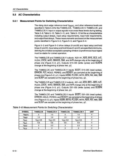
Table 5-8. Measurement Points for Switching Characteristics<br />
SYMBOL <strong>TI486</strong>SLC/E <strong>TI486</strong>SLC/E-V <strong>TI486</strong>DLC/E <strong>TI486</strong>DLC/E-V UNIT<br />
VREFC 2 1.5 2 1.5 V<br />
VREF 1.5 1.2 1.5 1.2 V<br />
VIHC VCC-Q·8 VCC-0.5 VCC-Q·8 VCC-Q·5 V<br />
VILC 0.8 0.6 0.8 0.6 V<br />
VIHD 3 2.3 3 2.3 V<br />
VILD 0 0 0 0 v<br />
5-10 Electrical Specifications


