

TI486 Microprocessor - Al Kossow's Bitsavers
TI486 Microprocessor - Al Kossow's Bitsavers
TI486 Microprocessor - Al Kossow's Bitsavers

You also want an ePaper? Increase the reach of your titles
YUMPU automatically turns print PDFs into web optimized ePapers that Google loves.
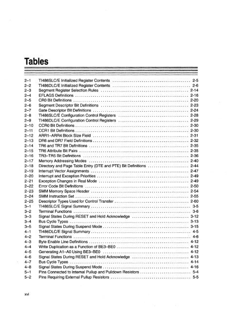
Tables<br />
2-1 <strong>TI486</strong>SLC/E Initialized Register Contents ........................................ 2-5<br />
2-2 <strong>TI486</strong>DLC/E Initialized Register Contents ........................................ 2-6<br />
2-3 Segment Register Selection Rules ............................................. 2-14<br />
2-4 EFLAGS Definitions .......... " .... " ........................................ 2-16<br />
2-5 CRO Bit Definitions ........................................................... 2-20<br />
2-6 Segment Descriptor Bit Definitions ............................................. 2-23<br />
2-7 Gate Descriptor Bit Definitions ................................................. 2-24<br />
2-8 <strong>TI486</strong>SLC/E Configuration Control Registers .................................... 2-28<br />
2-9 <strong>TI486</strong>DLC/E Configuration Control Registers .................................... 2-29<br />
2-10 CCRO Bit Definitions ....... , .. " ............................. " .... " .... '" .. 2-30<br />
2-11 CCR1 Bit Definitions .......................................................... 2-30<br />
2-12 ARR1-ARR4 Block Size Field ................................................. 2-31<br />
2-13 DR6 and DR7 Field Definitions. . . . . . . . . . . . . . . . . . . . . . . . . . . . . . . . . . . . . . . . . . . . . . . .. 2-32<br />
2-14 TR6 and TR7 Bit Definitions ................................................... 2-35<br />
2-15 TR6 Attribute Bit Pairs ........................................................ 2-35<br />
2-16 TR3-TR5 Bit Definitions ...................................................... 2-36<br />
2-17 Memory Addressing Modes ................................................... 2-40<br />
2-18 Directory and Page Table Entry (DTE and PTE) Bit Definitions ..................... 2-44<br />
2-19 Interrupt Vector Assignments ......................... '" .... '" ............... 2-47<br />
2-20 Interrupt and Exception Priorities ........................................... '.' .. 2-49<br />
2-21 Exception Changes in Real Mode ............................ '" ............... 2-49<br />
2-22 Error Code Bit Definitions ..................................................... 2-50<br />
2-23 SMM Memory Space Header ................................................... 2-54<br />
2-24 SMM Instruction Set .......................................................... 2-55<br />
2-25 Descriptor Types Used for Control Transfer. . . . . . . . . . . . . . . . . . . . . . . . . . . . . . . . . . . . .. 2-60<br />
3-1 <strong>TI486</strong>SLC/E Signal Summary . . . . . . . . . . . . . . . . . . . . . . . . . . . . . . . . . . . . . . . . . . . . . . . . . .. 3-5<br />
3-2 Terminal Functions ............................................................ 3-6<br />
3-3 Signal States During RESET and Hold Acknowledge ............................. 3-12<br />
3-4 Bus Cycle Types .... . . . . . . . . . . . . . . . . . . . . . . . . . . . . . . . . . . . . . . . . . . . . . . . . . . . . . . . .. 3-13<br />
3-5 Signal States During Suspend Mode. . . . . . . . . . . . . . . . . . . . . . . . . . . . . . . . . . . . . . . . . . .. 3-15<br />
4-1 <strong>TI486</strong>DLC/E Signal Summary. . . . . . . . . . . . . . . . . . . . . . . . . . . . . . . . . . . . . . . . . . . . . . . . . .. 4-5<br />
4-2 Terminal Functions ............................................................. 4-6<br />
4-3 Byte Enable Line Definitions . . . . . . . . . . . . . . . . . . . . . . . . . . . . . . . . . . . . . . . . . . . . . . . . . .. 4-12<br />
4-4 Write Duplication as a Function of BE3-BEO ............. '" ..................... 4-12<br />
4-5 Generating A 1-AO Using BE3-BEO ............................................ 4-12<br />
4-6 Signal States During RESET and Hold Acknowledge ............................. 4-13<br />
4-7 Bus Cycle Types ...... , ...................................................... 4-14<br />
4-8 Signal States During Suspend Mode. . . . . . . . . . . . . . . . . . . . . . . . . . . . . . . . . . . . . . . . . . .. 4-16<br />
5-1 Pins Connected to Internal Pullup and Pulldown Resistors. . . . . . . . . . . . . . . . . . . . . . . . .. 5-4<br />
5-2 Pins Requiring External Pullup Resistors . . . . . . . . . . . . . .. . . . . . . . . . . . . . . . . . . . . . . . . .. 5-5<br />
xvi


