

TI486 Microprocessor - Al Kossow's Bitsavers
TI486 Microprocessor - Al Kossow's Bitsavers
TI486 Microprocessor - Al Kossow's Bitsavers

You also want an ePaper? Increase the reach of your titles
YUMPU automatically turns print PDFs into web optimized ePapers that Google loves.
Overview<br />
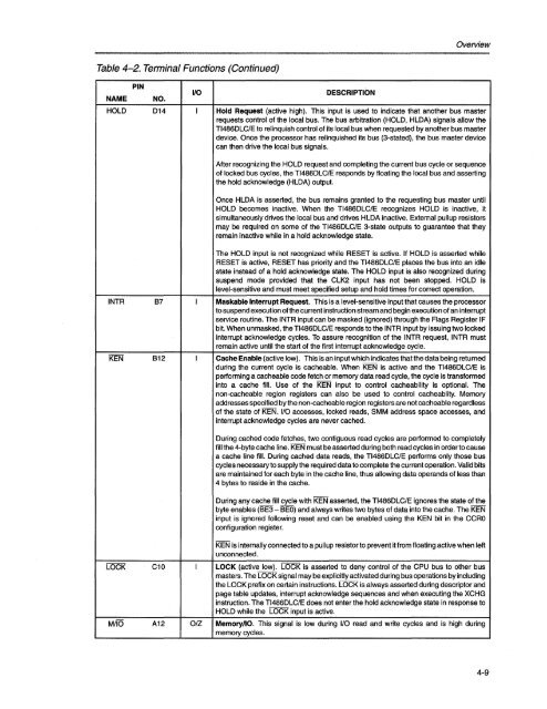
Table 4-2. Terminal Functions (Continued)<br />
NAME<br />
PIN<br />
NO.<br />
1/0<br />
DESCRIPTION<br />
HOLD D14 I Hold Request (active high). This input is used to indicate that another bus master<br />
requests control of the local bus. The bus arbitration (HOLD, HLDA) signals allow the<br />
<strong>TI486</strong>DLC/E to relinquish control of its local bus when requested by another bus master<br />
device. Once the processor has relinquished its bus (3-stated), the bus master device<br />
can then drive the local bus signals.<br />
After recognizing the HOLD request and completing the current bus cycle or sequence<br />
of locked bus cycles, the <strong>TI486</strong>DLC/E responds by floating the local bus and asserting<br />
the hold acknowledge (HLDA) output.<br />
Once HLDA is asserted, the bus remains granted to the requesting bus master until<br />
HOLD becomes inactive. When the <strong>TI486</strong>DLC/E recognizes HOLD is inactive, it<br />
simultaneously drives the local bus and drives HLDA inactive. External pullup resistors<br />
may be required on some of the <strong>TI486</strong>DLC/E 3-state outputs to guarantee that they<br />
remain inactive while in a hold acknowledge state.<br />
The HOLD input is not recognized while RESET is active. If HOLD is asserted while<br />
RESET is active, RESET has priority and the <strong>TI486</strong>DLC/E places the bus into an idle<br />
state instead of a hold acknowledge state. The HOLD input is also recognized during<br />
suspend mode provided that the CLK2 input has not been stopped. HOLD is<br />
level-sensitive and must meet specified setup and hold times for correct operation.<br />
INTR B7 I Maskable Interrupt Request. This is a level-sensitive input that causes the processor<br />
to suspend execution ofthe current instruction stream and begin execution of an interrupt<br />
service routine. The INTR input can be masked (ignored) through the Flags Register IF<br />
bit. When unmasked, the <strong>TI486</strong>DLC/E responds to the INTR input by issuing two locked<br />
interrupt acknowledge cycles. To assure recognition of the INTR request, INTR must<br />
remain active until the start of the first interrupt acknowledge cycle.<br />
KEN B12 I Cache Enable (active low). This is an input which indicates that the data being returned<br />
during the current cycle is cacheable. When KEN is active and the <strong>TI486</strong>DLC/E is<br />
performing a cacheable code fetch or memory data read cycle, the cycle is transformed<br />
into a cache fill. Use of the KEN input to control cacheability is optional. The<br />
non-cacheable region registers can also be used to control cacheablity. Memory<br />
addresses specified by the non-cacheable region registers are not cacheable regardless<br />
of the state of KEN. I/O accesses, locked reads, SMM address space accesses, and<br />
interrupt acknowledge cycles are never cached.<br />
During cached code fetches, two contiguous read cycles are performed to completely<br />
fill the 4-byte cache line. KEN must be asserted during both read cycles in order to cause<br />
a cache line fill. During cached data reads, the <strong>TI486</strong>DLC/E performs only those bus<br />
cycles necessary to supply the required data to complete the current operation. Valid bits<br />
are maintained for each byte in the cache line, thus allowing data operands of less than<br />
4 bytes to reside in the cache.<br />
During any cache fill cycle with KEN asserted, the <strong>TI486</strong>DLC/E ignores the state of the<br />
byte enables (BE3 - BEO) and always writes two bytes of data into the cache. The KEN<br />
input is ignored following reset and can be enabled using the KEN bit in the CCRO<br />
configuration register.<br />
KEN is internally connected to a pullup resistor to prevent it from floating active when left<br />
unconnected.<br />
LOCK C10 I LOCK (active low). LOCK is asserted to deny control of the CPU bus to other bus<br />
masters. The LOCK signal may be explicitly activated during bus operations by including<br />
the LOCK prefix on certain instructions. LOCK is always asserted during descriptor and<br />
page table updates, interrupt acknowledge sequences and when executing the XCHG<br />
instruction. The <strong>TI486</strong>DLC/E does not enter the hold acknowledge state in response to<br />
HOLD while the LOCK input is active.<br />
MilO A12 01Z Memory/lO. This signal is low during I/O read and write cycles and is high during<br />
memory cycles.<br />
4-9


