- Page 1:
MOSAIQ User’s Guide MOSAIQ Versio
- Page 4 and 5:
PUBLISHED BY: Elekta Impac Software
- Page 6 and 7:
MOSAIQ User’s Guide Entering Asse
- Page 8 and 9:
MOSAIQ User’s Guide Working with
- Page 10 and 11:
MOSAIQ User’s Guide Managing the
- Page 12 and 13:
MOSAIQ User’s Guide Site Setup Ve
- Page 15 and 16:
Introduction MOSAIQ User’s Guide
- Page 17 and 18:
Disclaimer Training Introduction El
- Page 19 and 20:
Notes, Hints, and Warnings Note exa
- Page 21 and 22:
Abbreviations and Acronyms BEV Beam
- Page 23 and 24:
CHAPTER 1: International Formats In
- Page 25 and 26:
Configuring Department Setup CHAPTE
- Page 27 and 28:
WARNING CHAPTER 1: International Fo
- Page 29 and 30:
CHAPTER 2: MOSAIQ Online Help MOSAI
- Page 31 and 32:
MOSAIQ User’s Guide CHAPTER 3: Ge
- Page 33 and 34:
CHAPTER 3: General Clinical Chartin
- Page 35 and 36:
CHAPTER 3: General Clinical Chartin
- Page 37 and 38:
CHAPTER 3: General Clinical Chartin
- Page 39 and 40:
Entering and Completing Course Info
- Page 41 and 42:
3 In the New Status group, click Ap
- Page 43 and 44:
CHAPTER 3: General Clinical Chartin
- Page 45 and 46:
Using the Diagnosis and Staging Tab
- Page 47 and 48:
Adding Oncology Details CHAPTER 3:
- Page 49 and 50:
Adding Assessments CHAPTER 3: Gener
- Page 51 and 52:
The Pharmacy Ordering List CHAPTER
- Page 53 and 54:
In House Pickup External Pickup CHA
- Page 55 and 56:
Adding a New Entry to Favorites Adm
- Page 57 and 58:
Adding a Favorite While Creating a
- Page 59 and 60:
Viewing the Medications Formulary W
- Page 61 and 62:
Adding Drugs to a Formulary List CH
- Page 63 and 64:
MOSAIQ User’s Guide CHAPTER 4: MO
- Page 65 and 66:
Viewing Pharmacy Tabs CHAPTER 4: MO
- Page 67 and 68:
CHAPTER 4: MOSAIQ Medical Oncology
- Page 69 and 70:
Voiding an Order CHAPTER 4: MOSAIQ
- Page 71 and 72:
CHAPTER 4: MOSAIQ Medical Oncology
- Page 73 and 74:
Waving Orders from Quick Orders CHA
- Page 75 and 76:
Adjusting a Medication Dose CHAPTER
- Page 77 and 78:
Configuring the Pharmacy Label and
- Page 79 and 80:
Printing the Pharmacy Worksheet CHA
- Page 81 and 82:
Documenting IV Details CHAPTER 4: M
- Page 83 and 84:
Documenting VAD Details CHAPTER 4:
- Page 85 and 86:
Correcting Medication Documentation
- Page 87 and 88:
MOSAIQ User’s Guide CHAPTER 5: MO
- Page 89 and 90:
CHAPTER 5: MOSAIQ Radiation Oncolog
- Page 91 and 92:
CHAPTER 5: MOSAIQ Radiation Oncolog
- Page 93 and 94:
CHAPTER 5: MOSAIQ Radiation Oncolog
- Page 95 and 96:
CHAPTER 5: MOSAIQ Radiation Oncolog
- Page 97 and 98:
CHAPTER 5: MOSAIQ Radiation Oncolog
- Page 99 and 100:
CHAPTER 5: MOSAIQ Radiation Oncolog
- Page 101 and 102:
CHAPTER 5: MOSAIQ Radiation Oncolog
- Page 103 and 104:
CHAPTER 5: MOSAIQ Radiation Oncolog
- Page 105 and 106:
CHAPTER 5: MOSAIQ Radiation Oncolog
- Page 107 and 108:
CHAPTER 5: MOSAIQ Radiation Oncolog
- Page 109 and 110:
Adding Field Setup Information CHAP
- Page 111 and 112:
CHAPTER 5: MOSAIQ Radiation Oncolog
- Page 113 and 114:
Approving a Treatment Field CHAPTER
- Page 115 and 116:
Reviewing IMRT CHAPTER 5: MOSAIQ Ra
- Page 117 and 118:
CHAPTER 5: MOSAIQ Radiation Oncolog
- Page 119 and 120:
Setting Up Dose Tracking CHAPTER 5:
- Page 121 and 122: Adding Secondary Dose Tracking Site
- Page 123 and 124: Adding Prior Dose CHAPTER 5: MOSAIQ
- Page 125 and 126: 8. Click OK. CHAPTER 5: MOSAIQ Radi
- Page 127 and 128: 9. Click OK. CHAPTER 5: MOSAIQ Radi
- Page 129 and 130: CHAPTER 5: MOSAIQ Radiation Oncolog
- Page 131 and 132: Changing Treatment Session Due Date
- Page 133 and 134: CHAPTER 5: MOSAIQ Radiation Oncolog
- Page 135 and 136: CHAPTER 5: MOSAIQ Radiation Oncolog
- Page 137 and 138: Scheduling a QA Mode Treatment Sess
- Page 139 and 140: 3. Click Current in the Patient(s)
- Page 141 and 142: Reviewing eCHART Chart Check Notes
- Page 143 and 144: CHAPTER 6: MLC Fit MOSAIQ User’s
- Page 145 and 146: Creating an MLC Leaf Plan 1. Click
- Page 147 and 148: MLC Conversion CHAPTER 6: MLC Fit M
- Page 149 and 150: CHAPTER 6: MLC Fit The display may
- Page 151 and 152: CHAPTER 6: MLC Fit 8. In the Treatm
- Page 153 and 154: MOSAIQ User’s Guide CHAPTER 7: Im
- Page 155 and 156: CHAPTER 7: Image Management-ViewSta
- Page 157 and 158: CHAPTER 7: Image Management-ViewSta
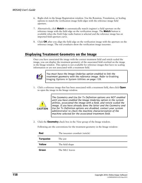
- Page 159 and 160: CHAPTER 7: Image Management-ViewSta
- Page 161 and 162: CHAPTER 7: Image Management-ViewSta
- Page 163 and 164: CHAPTER 7: Image Management-ViewSta
- Page 165 and 166: CHAPTER 7: Image Management-ViewSta
- Page 167 and 168: CHAPTER 7: Image Management-ViewSta
- Page 169 and 170: CHAPTER 7: Image Management-ViewSta
- Page 171: CHAPTER 7: Image Management-ViewSta
- Page 175 and 176: Request Review Status CHAPTER 7: Im
- Page 177 and 178: CHAPTER 7: Image Management-ViewSta
- Page 179 and 180: CHAPTER 7: Image Management-ViewSta
- Page 181 and 182: Print Scaling CHAPTER 7: Image Mana
- Page 183 and 184: Viewing and Enhancing Images CHAPTE
- Page 185 and 186: CHAPTER 7: Image Management-ViewSta
- Page 187 and 188: Using Ellipse Tools CHAPTER 7: Imag
- Page 189 and 190: Using the Fill and Color Options CH
- Page 191 and 192: CHAPTER 7: Image Management-ViewSta
- Page 193 and 194: CHAPTER 7: Image Management-ViewSta
- Page 195 and 196: CHAPTER 7: Image Management-ViewSta
- Page 197 and 198: CHAPTER 7: Image Management-ViewSta
- Page 199 and 200: CHAPTER 7: Image Management-ViewSta
- Page 201 and 202: CHAPTER 7: Image Management-ViewSta
- Page 203 and 204: CHAPTER 7: Image Management-ViewSta
- Page 205 and 206: CHAPTER 7: Image Management-ViewSta
- Page 207 and 208: CHAPTER 7: Image Management-ViewSta
- Page 209 and 210: CHAPTER 7: Image Management-ViewSta
- Page 211 and 212: CHAPTER 7: Image Management-ViewSta
- Page 213 and 214: CHAPTER 7: Image Management-ViewSta
- Page 215 and 216: CHAPTER 7: Image Management-ViewSta
- Page 217 and 218: Curve Registration CHAPTER 7: Image
- Page 219 and 220: CHAPTER 7: Image Management-ViewSta
- Page 221 and 222: Setup Alerts CHAPTER 7: Image Manag
- Page 223 and 224:
CHAPTER 7: Image Management-ViewSta
- Page 225 and 226:
CHAPTER 7: Image Management-ViewSta
- Page 227 and 228:
Localization Trend Review CHAPTER 7
- Page 229 and 230:
CHAPTER 7: Image Management-ViewSta
- Page 231 and 232:
Completing the Setup Offset CHAPTER
- Page 233 and 234:
CHAPTER 7: Image Management-ViewSta
- Page 235 and 236:
CHAPTER 8: MOSAIQ DICOM MOSAIQ User
- Page 237 and 238:
DCM System Preferences CHAPTER 8: M
- Page 239 and 240:
Setting Up Auto-forwarding for a DI
- Page 241 and 242:
CHAPTER 8: MOSAIQ DICOM Do this…
- Page 243 and 244:
In the… To… CHAPTER 8: MOSAIQ D
- Page 245 and 246:
DICOM AE Edit CHAPTER 8: MOSAIQ DIC
- Page 247 and 248:
For DICOM Images Group These contro
- Page 249 and 250:
CHAPTER 9: MOSAIQ Oncology PACS MOS
- Page 251 and 252:
DICOM Configuration Admin Rights CA
- Page 253 and 254:
CHAPTER 9: MOSAIQ Oncology PACS The
- Page 255 and 256:
Manage Data CHAPTER 9: MOSAIQ Oncol
- Page 257 and 258:
Doing a Check for Eligible Patients
- Page 259 and 260:
Selecting Patients CHAPTER 9: MOSAI
- Page 261 and 262:
CHAPTER 9: MOSAIQ Oncology PACS 3.
- Page 263 and 264:
Selecting Images b. Click the Refre
- Page 265 and 266:
Managing the Restore Queue CHAPTER
- Page 267 and 268:
CHAPTER 10: SEQUENCER MOSAIQ User
- Page 269 and 270:
QA Mode Field Change Warnings (chec
- Page 271 and 272:
10. Click Close in the Treatment De
- Page 273 and 274:
CHAPTER 10: SEQUENCER 7. Click Reco
- Page 275 and 276:
Select a Patient for Treatment CHAP
- Page 277 and 278:
Treatment Chart CHAPTER 10: SEQUENC
- Page 279 and 280:
Unhiding a Treatment Field CHAPTER
- Page 281 and 282:
CHAPTER 10: SEQUENCER 3. In the Tre
- Page 283 and 284:
CHAPTER 10: SEQUENCER 6. Click the
- Page 285 and 286:
Consolidated Field Sequences (CFS)
- Page 287 and 288:
Using the Override Feature CHAPTER
- Page 289 and 290:
CHAPTER 10: SEQUENCER The prescript
- Page 291 and 292:
Troubleshooting Abnormal Treatment
- Page 293 and 294:
Appendix A: Contact and Regulatory
- Page 295 and 296:
MOSAIQ User’s Guide Appendix B: W
- Page 297 and 298:
Appendix B: Warnings and Cautions i
- Page 299 and 300:
Appendix B: Warnings and Cautions i
- Page 301 and 302:
Appendix B: Warnings and Cautions i
- Page 303 and 304:
When Rounding Error 2 is exceeded:
- Page 305 and 306:
MOSAIQ User’s Guide Appendix C: I
- Page 307 and 308:
MLC Fit Intended Use Appendix C: In
- Page 309 and 310:
Appendix D: Measurement of Accuracy
- Page 311 and 312:
Index A Abbreviations/Acronyms, 7 A
- Page 313 and 314:
DICOM AE Edit, 231 DICOM Communicat
- Page 315 and 316:
using, 130 MLC leaf plan report, 13
- Page 317 and 318:
selecting patients for treatment, 2
- Page 319 and 320:
Index Copyright 2010, Elekta Impac


