- Page 1 and 2:
,0 *• DATSUN - «; fjffl rfi i Sf
- Page 3 and 4:
SECTION Gl c If DATSUN 280Z r^lODEL
- Page 5 and 6:
General Information IDENTIFICATION
- Page 7 and 8:
i General Information 1 LUBRICANT S
- Page 9 and 10:
.1ft. SECTION ET (• «I DATSUN 28
- Page 11 and 12:
Engine Tune-up v ET012 Fig. ET-7 Te
- Page 13 and 14:
CHECKING OPERATING PARTS OF DISTRIB
- Page 15 and 16:
Engine Tune-up Rubber fuel hoses in
- Page 17 and 18:
Engine Tune-up EMISSION CONTROL SYS
- Page 19 and 20:
Engine Tune-up Checking vacuum cont
- Page 21 and 22:
^ CHECKING SPARK TIMING CONTROL SYS
- Page 23 and 24:
Engine Tune-up CHECKING TRANSMISSIO
- Page 25 and 26:
Engine Tune-up 4. Supply fresh air
- Page 27 and 28:
^ 2. If voltmeter reading is not as
- Page 29 and 30:
Engine Tune-up 6. Check continuity
- Page 31 and 32:
Engine Tune-up Checking catalyzer t
- Page 33 and 34:
Engine Tune-up Note: Do not heat fl
- Page 35 and 36:
Engine Tune-up TROUBLE DIAGNOSES AN
- Page 37 and 38:
Engine Tune-up Condition Probable c
- Page 39 and 40:
Engine Tune-up Condition Probable c
- Page 41 and 42:
Engine Tune-up Condition Excessive
- Page 43 and 44:
RL'#«W frs •: K?A: *- •f SECTI
- Page 45 and 46:
supported by No. 2, 3 and 4 camshaf
- Page 47 and 48:
17. Remove intake manifold and heat
- Page 49 and 50:
Engine Mechanical INSPECTION AND RE
- Page 51 and 52:
ROCKER ARM AND VALVE ROCKER PIVOT C
- Page 53 and 54:
Engine Mechanical 3. Machine cylind
- Page 55 and 56:
Engine Mechanical 1 20 (0.79) 60 (2
- Page 57 and 58:
Engine Mechanical PISTONS, PISTON P
- Page 59 and 60:
Engine Mechanical L28 Crankshaft be
- Page 61 and 62:
Engine Mechanical Connecting rod be
- Page 63 and 64:
Engine Mechanical ENGINE ASSEMBLY C
- Page 65 and 66:
Engine Mechanical 5. Install main b
- Page 67 and 68:
Fig. EM-105 Installing crankshaft p
- Page 69 and 70:
Engine Mechanical 44. Install engin
- Page 71 and 72:
Engine Mechanical SPECIFICATIONS Mo
- Page 73 and 74:
Engine Mechanical c) Connecting rod
- Page 75 and 76:
Engine Mechanical TROUBLE DfAGNOSES
- Page 77 and 78:
Engine Mechanical SPECIAL SERVICE T
- Page 79 and 80:
Engine Mechanical No. Tool number &
- Page 81 and 82:
«i">! fTC* **£' :. Si. SECTION EL
- Page 83 and 84:
Punch mark ' Oil hole EL009 Fig.EL-
- Page 85 and 86:
Engine Lubrication System SERVICE D
- Page 87 and 88:
SECTION CO '%••' DATSUN 280Z MO
- Page 89 and 90:
Cooling System COOLANT LEVEL The co
- Page 91 and 92:
INSPECTION Check Tem-coupling for o
- Page 93 and 94:
Cooling System SPECIFICATIONS Engin
- Page 95 and 96:
SERVlCt MANUAL DATSUN 280Z MODEL S3
- Page 97 and 98:
Engine Fuel ELECTRONIC FUEL INJECTI
- Page 99 and 100:
• RjaFLOW + - AIR ROW ^ VACUUM
- Page 101 and 102:
DROPPING RESISTOR (1) DROPPING RESI
- Page 103 and 104:
AIR FLOW METER THROTTLE VALVE SWITC
- Page 105 and 106:
Engine Fuel I) COLD START VALVE INC
- Page 107 and 108:
Engine Fuel © TERMINAL © TERMINAL
- Page 109 and 110:
Engine Fuel Fig. EF-20 Dropping res
- Page 111 and 112:
Engine Fuel Direction of bimetal mo
- Page 113 and 114:
Engine Fuel If a continuity test on
- Page 115 and 116:
Connector and harness continuity ch
- Page 117 and 118:
Use the same procedure as in step 9
- Page 119 and 120:
THERMOTIME SW 1 COLD START VALVE I
- Page 121 and 122:
THERMOTIME SW. "~l COLO START VALVE
- Page 123 and 124:
THERMOTIME SW i 1 COLD START WATER
- Page 125 and 126:
THERMOTIME SW i 1 COLD START WATER
- Page 127 and 128:
THERMOTIME SW i 1 COLD START VALVE
- Page 129 and 130:
THERMOTIME SW i 1 COLD START VALVE
- Page 131 and 132:
THERMOTIME SW. I 1 COLD START VALVE
- Page 133 and 134:
THERMOTIME SW i 1 COLD START VALVE
- Page 135 and 136:
Engine Fuel in oo r> ri2a!2Di^9 0 >
- Page 137 and 138:
Engine Fuel o m o p N c o i o ' J '
- Page 139 and 140:
THERMOTIME SW i 1 46 COLD START VAL
- Page 141 and 142:
THERMOTIME SW i 1 COLD START WATER
- Page 143 and 144:
THERMOTIME SW. i 1 COLC START VALVE
- Page 145 and 146:
CHECKING FUNCTIONAL PARTS 1. Contro
- Page 147 and 148:
Engine Fuel 4-1. Checking on engine
- Page 149 and 150:
Engine Fuel •0+ (J3!5 EF408 Fig.
- Page 151 and 152:
Discharge pressure check 1. Disconn
- Page 153 and 154:
4. Make sure that idle adjust screw
- Page 155 and 156:
Engine Fuel Caution: When connectin
- Page 157 and 158:
11. Fuel damper 1. Disconnect groun
- Page 159 and 160:
15. Air regulator 1. Disconnect gro
- Page 161 and 162:
SECTION EC DATSUN 280Z MODEL S30 SE
- Page 163 and 164: Emission Control System EXHAUST EMI
- Page 165 and 166: BOOST CONTROLLED DECELERATION DEVIC
- Page 167 and 168: Emission Control System B.C.D.D. so
- Page 169 and 170: TRANSMISSION CONTROLLED VACUUM ADVA
- Page 171 and 172: Emission Control System 1 Intake ma
- Page 173 and 174: Water temperature switch and E.G.R.
- Page 175 and 176: Emission Control System By means of
- Page 177 and 178: OPERATION Catalytic converter The e
- Page 179 and 180: Emission Control System Catalyzer w
- Page 181 and 182: Turn ignition switch to the IG posi
- Page 183 and 184: 4. If voltmeter reading is not as s
- Page 185 and 186: Emission Control System 7. Check co
- Page 187 and 188: Emission Control System When cataly
- Page 189 and 190: Emission Control System Floor senso
- Page 191 and 192: Emission Control System If test res
- Page 193 and 194: SECTION EE DATSUN MODEL 280Z S30 SE
- Page 195 and 196: Engine Electrical System BATTERY FR
- Page 197 and 198: Engine Electrical System STARTING M
- Page 199 and 200: Engine Electrical System CONSTRUCTI
- Page 201 and 202: Engine Electrical System TERMINAL C
- Page 203 and 204: TEST PERFORMANCE TEST Starter motor
- Page 205 and 206: Engine Electrical System Condition
- Page 207 and 208: Engine Electrical System ALTERNATOR
- Page 209 and 210: ROTOR INSPECTION 1. Continuity test
- Page 211 and 212: ALTERNATOR TEST Before conducting a
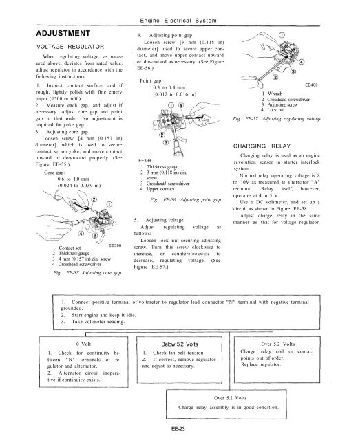
- Page 213: Engine Electrical System MEASUREMEN
- Page 217 and 218: Engine Electrical System TROUBLE DI
- Page 219 and 220: Engine Electrical System DISTRIBUTO
- Page 221 and 222: Engine Electrical System Fig. EE-64
- Page 223 and 224: Engine Electrical System 4. Apply g
- Page 225 and 226: Engine Electrical System Transistor
- Page 227 and 228: Engine Electrical System EE379 Fig.
- Page 229 and 230: Engine Electrical System Criterion:
- Page 231 and 232: Ignition switch ©K^ BL BW 6 \ Wate
- Page 233 and 234: Engine Electrical System ® -®- -
- Page 235 and 236: Engine Electrical System EE387 Fig.
- Page 237 and 238: Engine Electrical System IGNITION C
- Page 239 and 240: Engine Electrical System SERVICE DA
- Page 241 and 242: SERVICE MANUAL DATSUN 280Z MODEL S3
- Page 243 and 244: 12. Disconnect the following cables
- Page 245 and 246: ENGINE MOUNTING INSULATORS Three in
- Page 247 and 248: SERVICE MANUAL DATSUN 280Z MODEL S3
- Page 249 and 250: ( Clutch Flywheel and pressure plat
- Page 251 and 252: Clutch 4 5 to 5.0 mm (0.18 to 0.20
- Page 253 and 254: 1. Pedal head rubber 2. Return spri
- Page 255 and 256: Clutch SERVICE DATA AND SPECIFICATI
- Page 257 and 258: Clutch Condition Probable cause and
- Page 259: Clutch No. Tool number & tool name
- Page 262 and 263: Transmission 4-SPEED TRANSMISSION (
- Page 264 and 265:
Fig. TM-7 Removing main drive beari
- Page 266 and 267:
Transmission Countershaft assembly
- Page 268 and 269:
Coat oil seal and bushing with gear
- Page 270 and 271:
7. Install mainshaft reverse gear,
- Page 272 and 273:
GENERAL SPECIFICATIONS Transmission
- Page 274 and 275:
Transmission TROUBLE DIAGNOSES AND
- Page 276 and 277:
i Transmission Tool number & tool n
- Page 278 and 279:
Automatic Transmission DESCRIPTION
- Page 280 and 281:
Automatic Transmission HYDRAULIC CO
- Page 282 and 283:
the space from (1) to (15) increase
- Page 284 and 285:
1st-2nd shift valve (FSV) The FSV i
- Page 286 and 287:
space from the throttle pressure (1
- Page 288 and 289:
Automatic Transmission rm AT094 1 P
- Page 290 and 291:
i Automatic Transmission "P" RANGE
- Page 292 and 293:
Automatic Transmission "R" RANGE (R
- Page 294 and 295:
Automatic Transmission "N" RANGE (N
- Page 296 and 297:
"D " RANGE (LOW GEAR) The low gear
- Page 298 and 299:
Automatic Transmission "D " RANGE (
- Page 300 and 301:
Automatic Transmission "D 3 " RANGE
- Page 302 and 303:
Automatic Transmission "D" RANGE KI
- Page 304 and 305:
"2" RANGE (2ND GEAR) In "2" range t
- Page 306 and 307:
Automatic Transmission "1 " RANGE (
- Page 308 and 309:
Automatic Transmission "1" range (2
- Page 310 and 311:
Automatic Transmission AT116 Fig. A
- Page 312 and 313:
Automatic Transmission MAJOR REPAIR
- Page 314 and 315:
Automatic Transmission AT 133 Fig.
- Page 316 and 317:
Adjustment of front end play Select
- Page 318 and 319:
3. Blow out piston by directing a j
- Page 320 and 321:
Automatic Transmission [Replace if
- Page 322 and 323:
Automatic Transmission Valve spring
- Page 324 and 325:
Automatic Transmission TROUBLE DIAG
- Page 326 and 327:
Check whether the reverse lamp and
- Page 328 and 329:
Automatic Transmission CHECKING SPE
- Page 330 and 331:
Automatic Transmission TROUBLE-SHOO
- Page 332 and 333:
Automatic Transmission Trouble A B
- Page 334 and 335:
Automatic Transmission Order Test i
- Page 336 and 337:
Low & reverse brake Brake band Auto
- Page 338 and 339:
Automatic Transmission SPECIAL SERV
- Page 340 and 341:
Automatic Transmission Tool number
- Page 342 and 343:
Propeller Shaft & Differential Carr
- Page 344 and 345:
Propeller Shaft & Differential Carr
- Page 346 and 347:
Propeller Shaft & Differential Carr
- Page 348 and 349:
Propeller Shaft & Differential Carr
- Page 350 and 351:
Propeller Shaft & Differential Carr
- Page 352 and 353:
Propeller Shaft & Differential Carr
- Page 354 and 355:
Propeller Shaft & Differential Carr
- Page 356 and 357:
Propeller Shaft & Differential Carr
- Page 358 and 359:
Propeller Shaft & Differential Carr
- Page 360 and 361:
Propeller Shaft & Differential Carr
- Page 362 and 363:
Propeller Shaft & Differential Carr
- Page 364 and 365:
Front Axle & Front Suspension DESCR
- Page 366 and 367:
8. Install hub cap. WHEEL ALIGNMENT
- Page 368 and 369:
Front Axle & Front Suspension 1 Out
- Page 370 and 371:
Front Axle & Front Suspension a) In
- Page 372 and 373:
Front Axle & Front Suspension i REM
- Page 374 and 375:
Notes: a. When tightening gland pac
- Page 376 and 377:
Front Axle & Front Suspension INSPE
- Page 378 and 379:
Front Axle & Front Suspension Coil
- Page 380 and 381:
Front Axle & Front Suspension TROUB
- Page 382 and 383:
Front Axle & Front Suspension Condi
- Page 384 and 385:
Front Axle & Front Suspension No. T
- Page 386 and 387:
Rear Axle & Rear Suspension DESCRIP
- Page 388 and 389:
Rear Axle & Rear Suspension REAR AX
- Page 390 and 391:
Rear Axle & Rear Suspension REMOVAL
- Page 392 and 393:
Rear Axle & Rear Suspension 2. Jack
- Page 394 and 395:
10. Remove link mounting rear brack
- Page 396 and 397:
Rear Axle & Rear Suspension Front d
- Page 398 and 399:
Rear Axle & Rear Suspension SPECIAL
- Page 401 and 402:
SECTION BR DATSUN 280Z MODEL S30 SE
- Page 403 and 404:
BRAKE PEDAL The brake pedal is inst
- Page 405 and 406:
BRAKE LINE The brake lines branched
- Page 407 and 408:
1, Appearance of NP-valve for S30 s
- Page 409 and 410:
INSPECTION 1. fl?&> pad with carbon
- Page 411 and 412:
Brake System REPLACING BRAKE SHOE R
- Page 413 and 414:
Brake System 1. When assembling whe
- Page 415 and 416:
Brake System MASTER-VAC CONTENTS DE
- Page 417 and 418:
described under "Inspection" before
- Page 419 and 420:
Retainer Brake System 3. Before ins
- Page 421 and 422:
Brake System Tightening torque Unit
- Page 423 and 424:
Brake System Condition Probable cau
- Page 425:
Brake System SPECIAL SERVICE TOOLS
- Page 428 and 429:
Wheel and Tire WHEEL AND TIRE CONTE
- Page 430 and 431:
When dynamic balance is required, t
- Page 433 and 434:
M SECTION ST DATSUN 280Z MODEL S30
- Page 435 and 436:
impact. Thus, if the car should be
- Page 437 and 438:
Steering System 1 Steering wheel 2
- Page 439 and 440:
Steering System Note: Do not assemb
- Page 441 and 442:
Steering System Side rod inner ball
- Page 443 and 444:
Steering System Clearance 2 mm (0.0
- Page 445 and 446:
Steering System TIGHTENING TORQUE C
- Page 447 and 448:
Steering System 3. Instability of c
- Page 449:
Steering System Possible cause Corr
- Page 452 and 453:
ngine Control, Fuel & Exhaust Syste
- Page 454 and 455:
Engine Control, Fuel & Exhaust Syst
- Page 456 and 457:
Engine Control, Fuel & Exhaust Syst
- Page 458 and 459:
Engine Control, Fuel & Exhaust Syst
- Page 461 and 462:
T£t> *:n • SECTION BF •» DATS
- Page 463 and 464:
Body BF342A Fig. BF-2 Structure of
- Page 465 and 466:
Body Fig. BF-3 Underbody alignment
- Page 467 and 468:
Body BUMPER AND RADIATOR GRILLE CON
- Page 469 and 470:
Body effect]. See Figure BF-10. (5)
- Page 471 and 472:
Fig. BF-19 JF356A Adjusting hood at
- Page 473 and 474:
Body COWL TOP GRILLE AND FRONT FEND
- Page 475 and 476:
ADJUSTMENT TAIL GATE HINGE 1. The f
- Page 477 and 478:
REMOVAL AND INSTALLATION Left door
- Page 479 and 480:
Inside door handle free play 1. Par
- Page 481 and 482:
Body WINDSHIELD GLASS CONTENTS FRON
- Page 483 and 484:
Body TAIL GATE GLASS The instructio
- Page 485 and 486:
Body SEAT BELT CONTENTS DESCRIPTION
- Page 487 and 488:
Body FLOOR CONSOLE REMOVAL AND INST
- Page 489 and 490:
Body BODY SEALING DESCRIPTION Seale
- Page 491 and 492:
SERVICE MANUAL DATSUN 280Z MODEL S3
- Page 493 and 494:
The main cable of each system is ge
- Page 495 and 496:
INSPECTION Inspect all electrical c
- Page 497 and 498:
To antenna motor To rear side marke
- Page 499 and 500:
Body Electrical System LIGHTING AND
- Page 501 and 502:
CIRCUIT DIAGRAM OF LIGHTING SYSTEM
- Page 503 and 504:
Body Electrical System Hazard warni
- Page 505 and 506:
Body Electrical System Clearance an
- Page 507 and 508:
Body Electrical System Meter illumi
- Page 509 and 510:
Body Electrical System Interior lam
- Page 511 and 512:
Body Electrical System Map lamp sys
- Page 513 and 514:
FRONT COMBINATION LAMP Body Electri
- Page 515 and 516:
Body Electrical System LAMP BODY RE
- Page 517 and 518:
COMBINATION SWITCH The combination
- Page 519 and 520:
Body Electrical System \ 1 2 3 4 5
- Page 521 and 522:
Body Electrical System TROUBLE DIAG
- Page 523 and 524:
Body Electrical System 1 2 3 4 5 6
- Page 525 and 526:
Body Electrical System Water temper
- Page 527 and 528:
^ Body Electrical System Brake warn
- Page 529 and 530:
Bulb replacement Pull out socket, w
- Page 531 and 532:
5. Pulling gauge out backward, disc
- Page 533 and 534:
Body Electrical System Hand brake s
- Page 535 and 536:
Body Electrical System Condition Fu
- Page 537 and 538:
Body Electrical System Bl LEVEL AIR
- Page 539 and 540:
Body Electrical System 7. Remove tw
- Page 541 and 542:
Body Electrical System Heater cock
- Page 543 and 544:
Body Electrical System Heater cock
- Page 545 and 546:
Body Electrical System Heater _=_ J
- Page 547 and 548:
Body Electrical System HORN DESCRIP
- Page 549 and 550:
Body Electrical System Horn AT STAR
- Page 551 and 552:
I Body Electrical System ADJUSTMENT
- Page 553 and 554:
TROUBLE DIAGNOSES AND CORRECTIONS B
- Page 555 and 556:
Body Electrical System Windshield w
- Page 557 and 558:
Body Electrical System "High" posit
- Page 559 and 560:
CIGARETTE LIGHTER DESCRIPTION The c
- Page 561 and 562:
REPLACEMENT Clock 1. Remove four sc
- Page 563 and 564:
Body Electrical System BE537 Defogg
- Page 565 and 566:
Body Electrical System i i- Ct < m
- Page 567 and 568:
Body Electrical System 3. Remove bo
- Page 569 and 570:
©*—® Js>J AT STARTER MOTOR 6 FU
- Page 571 and 572:
Body Electrical System Warning buzz
- Page 573 and 574:
Body Electrical System KICKDOWN SYS
- Page 575 and 576:
Body Electrical System 13 •5, tt
- Page 577 and 578:
Body Electrical System c '2 •Sf I
- Page 579 and 580:
Body Electrical System STARTER INTE
- Page 581 and 582:
Body Electrical System TROUBLE DIAG
- Page 583 and 584:
Body Electrical System SEAT SWITCH
- Page 585 and 586:
Body Electrical System SEAT BELT WA
- Page 587 and 588:
Inspection Remove two screws retain
- Page 589 and 590:
Body Electrical System Assistant's
- Page 591 and 592:
Body Electrical System Ignition swi
- Page 593 and 594:
Body Electrical System Neutral swit
- Page 595 and 596:
Body Electrical System Engine revol
- Page 597 and 598:
Body Electrical System Emergency sw
- Page 599 and 600:
Body Electrical System EMISSION WAR
- Page 601 and 602:
Body Electrical System TROUBLE SHOO
- Page 603:
Body Electrical System TROUBLE SHOO
- Page 606 and 607:
Air Conditioning DESCRIPTION CONTEN
- Page 608 and 609:
Air Conditioning REFRIGERATION SYST
- Page 610 and 611:
AIR FLOW AND VACUUM SYSTEM AIR FLOW
- Page 612 and 613:
Air Conditioning VENT (Ventilation)
- Page 614 and 615:
Air Conditioning HEATER (FRESH) pos
- Page 616 and 617:
Air Conditioning DEF (Defrost) posi
- Page 618 and 619:
Air Conditioning OFF POSITION Ignit
- Page 620 and 621:
Air Conditioning GENERAL SERVICE CO
- Page 622 and 623:
Air Conditioning r\ Low-pressure ga
- Page 624 and 625:
Air Conditioning DISCHARGING SYSTEM
- Page 626 and 627:
When charging liquefied refrigerant
- Page 628 and 629:
(3) Piping • Flared section of hi
- Page 630 and 631:
If system has been exposed to atmos
- Page 632 and 633:
. condition^ Atr Tightening torque
- Page 634 and 635:
Air Conditioning FAST IDLE ACTUATOR
- Page 636 and 637:
Air Conditioning 11. In the reverse
- Page 638 and 639:
Air Conditioning AC282 Fig. AC-53 1
- Page 640 and 641:
Air Conditioning VACUUM HOSE DIAGRA
- Page 642 and 643:
CIRCUIT DIAGRAM FOR AIR CONDITIONER
- Page 644 and 645:
Noisy Insufficient cooling Blower d
- Page 646 and 647:
Air Conditioning Condition Probable
- Page 648 and 649:
BLOWER MOTOR DIAGNOSES Air Conditio
- Page 650 and 651:
Air Conditioning COMPRESSOR CLUTCH
- Page 652 and 653:
Air Conditioning AIR CONDITIONER OP
- Page 654 and 655:
j VACUUM SYSTEM DIAGNOSES Air Condi
- Page 656 and 657:
Air Conditioning VACUUM SYSTEM DIAG
- Page 658 and 659:
Air Conditioning VACUUM SYSTEM DIAG
- Page 660 and 661:
Air comes out of defroster nozzles.
- Page 662 and 663:
Air Conditioning HOW TO INSTALL AIR
- Page 664 and 665:
Air Conditioning III. Install air c
- Page 666 and 667:
Air Conditioning 5. Installation of
- Page 668 and 669:
Air Conditioning COMPRESSOR CONTENT
- Page 670 and 671:
1 COMPRESSOR CLUTCH The most likely
- Page 672 and 673:
INSTALLATION 1. Make sure that the
- Page 674 and 675:
INSPECTION 1. Do not reuse old gask
- Page 676 and 677:
Air Conditioning SERVICE DATA AND S
- Page 678 and 679:
Air Conditioning SPECIAL SERVICE TO
- Page 680 and 681:
Air Conditioning Tool number & tool
- Page 682 and 683:
I A
- Page 684 and 685:
Service Equipment SERVICE EQUIPMENT
- Page 686 and 687:
Service Equipment No. Tool number T