CANoe DENoe - KEMT FEI TUKE
CANoe DENoe - KEMT FEI TUKE
CANoe DENoe - KEMT FEI TUKE

Create successful ePaper yourself
Turn your PDF publications into a flip-book with our unique Google optimized e-Paper software.
30<br />
1.3.12.3 Creating Network Node Models<br />
You create the network node models in the simulation setup. At the least, the model<br />
for the first node must send a message when the switch is activated, and therefore it<br />
may not be inserted in the measurement setup.<br />
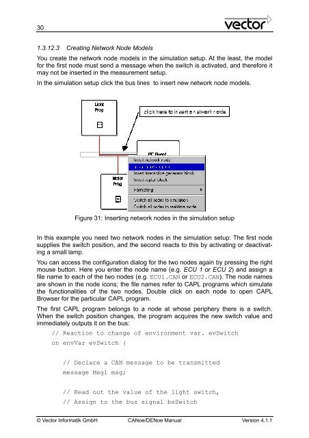
In the simulation setup click the bus lines to insert new network node models.<br />
Figure 31: Inserting network nodes in the simulation setup<br />
In this example you need two network nodes in the simulation setup: The first node<br />
supplies the switch position, and the second reacts to this by activating or deactivating<br />
a small lamp.<br />
You can access the configuration dialog for the two nodes again by pressing the right<br />
mouse button. Here you enter the node name (e.g. ECU 1 or ECU 2) and assign a<br />
file name to each of the two nodes (e.g. ECU1.CAN or ECU2.CAN). The node names<br />
are shown in the node icons; the file names refer to CAPL programs which simulate<br />
the functionalities of the two nodes. Double click on each node to open CAPL<br />
Browser for the particular CAPL program.<br />
The first CAPL program belongs to a node at whose periphery there is a switch.<br />
When the switch position changes, the program acquires the new switch value and<br />
immediately outputs it on the bus:<br />
// Reaction to change of environment var. evSwitch<br />
on envVar evSwitch {<br />
// Declare a CAN message to be transmitted<br />
message Msg1 msg;<br />
// Read out the value of the light switch,<br />
// Assign to the bus signal bsSwitch<br />
© Vector Informatik GmbH <strong>CANoe</strong>/<strong>DENoe</strong> Manual Version 4.1.1