Identification des mécanismes de fissuration dans un alliage d ...
Identification des mécanismes de fissuration dans un alliage d ...
Identification des mécanismes de fissuration dans un alliage d ...
You also want an ePaper? Increase the reach of your titles
YUMPU automatically turns print PDFs into web optimized ePapers that Google loves.
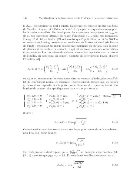
142 Modélisation <strong>de</strong> la <strong>fissuration</strong> et <strong>de</strong> l’influence <strong>de</strong> la microstructure<br />
Si d SWT est supérieur ou égal à l’<strong>un</strong>ité, l’amorçage est censé se produire au bout<br />
<strong>de</strong> N cycles. Si d SWT est inférieur à l’<strong>un</strong>ité, il n’y a pas <strong>de</strong> risque d’amorçage pour<br />
les N cycles considérés. En développant les expressions analytiques <strong>de</strong> σ max et<br />
<strong>de</strong> ε a , <strong>un</strong>e expression littérale du risque d’amorçage d SWT peut être formalisée.<br />
Fouvry et al. [61] et Fridrici [99] ont montré que l’application du critère SWT à<br />
<strong>un</strong> contact <strong>de</strong> fretting présentant <strong>un</strong> coefficient <strong>de</strong> frottement élevé (<strong>de</strong> l’ordre<br />
<strong>de</strong> l’<strong>un</strong>ité), produisait <strong>un</strong> risque d’amorçage maximum en surface, <strong>dans</strong> la zone<br />
<strong>de</strong> glissement en bordure <strong>de</strong> contact, ce qui est en accord avec nos observations<br />
expérimentales. Les contraintes <strong>de</strong> surfaces peuvent être exprimées avec la théorie<br />
<strong>de</strong> Mindlin, en supposant <strong>un</strong> contact élastique en déformations planes, d’après<br />
l’équation [57] :<br />
( (<br />
σ<br />
n x<br />
ij<br />
σ ij (x, y) = p , ))<br />
( ( y<br />
a a σ<br />
t x<br />
0 + µp , ))<br />
y<br />
ij a a<br />
0<br />
p 0 µp 0<br />
( (<br />
c σ<br />
t x<br />
ij<br />
− µp , )<br />
c c)<br />
y<br />
0<br />
a µp 0<br />
(4.3)<br />
où σij n et σt ij représentent les contraintes <strong>dans</strong> <strong>un</strong> contact cylindre/plan sous l’effet<br />
du chargement normal et tangentiel respectivement. Notons que les indices<br />
ij peuvent correspondre à n’importe quelle direction du repère <strong>de</strong> travail. En<br />
bordure <strong>de</strong> contact plus spécifiquement (à x = a et y = 0) on a :<br />
⎧<br />
⎧<br />
σ ⎪⎨<br />
xx(1, n 0) = 0 σ ⎪⎨<br />
xx(1, t 0) = 2µp 0<br />
σyy n (1, 0) = 0 σ<br />
σzz ⎪⎩<br />
n yy<br />
,<br />
t (1, 0) = 0<br />
(1, 0) = 0 σ<br />
σxy n (1, 0) = 0 zz ⎪⎩<br />
t (1, 0) = 2νµp et<br />
0<br />
σxy t (1, 0) = 0<br />
il vient :<br />
⎧<br />
⎪⎨<br />
⎪⎩<br />
σ t xx (a c , 0) = 2µp 0 a c − 2µp 0√<br />
(<br />
a<br />
c )2 − 1<br />
σ t yy (a c , 0) = 0<br />
σ t zz (a c , 0) = ν × σt xx (a c , 0)<br />
σ t xy (a c , 0) = 0<br />
σ xx (a, 0) = 2µp 0<br />
√1 − ( c a )2 (4.4)<br />
Cette équation peut être réécrite sous <strong>un</strong>e forme plus commo<strong>de</strong> en la combinant<br />
avec l’éq. (3.1) pour donner :<br />
σ xx (a, 0) = 2µp 0<br />
√<br />
Q ∗<br />
µ PS P<br />
(4.5)<br />
En configuration cylindre/plan, p 0 = ( )<br />
PE ∗ 1/2<br />
πR et l’analyse experimentale (cf.<br />
§3.1.1) a montré que µ PS = µ = 1.1. En combinant ces divers éléments, on a :<br />
σ xx (a, 0) = 2<br />
√<br />
µE∗ Q ∗<br />
πR<br />
(4.6)


