general instructions. - Limit Of Shunt
general instructions. - Limit Of Shunt
general instructions. - Limit Of Shunt

You also want an ePaper? Increase the reach of your titles
YUMPU automatically turns print PDFs into web optimized ePapers that Google loves.
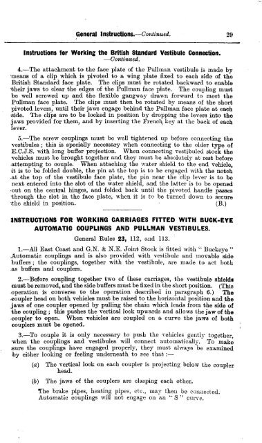
General Instructions.—Continued. 2 9<br />
Instructions tor Working the British Standard Vestibule Connection.<br />
—Continued.<br />
4.—The attachment to the face plate of the Pullman vestibule is made by<br />
means of a clip which is pivoted to a wing plate fixed to each side of the<br />
British Standard face plate. The clips must be rotated backward to enable<br />
their jaws to clear the edges of the Pullman face plate. The coupling must<br />
be well screwed up and the flexible gangway drawn forward to meet the<br />
Pullman face plate. The clips must then be rotated by means of the short<br />
pivoted levers, until their jaws engage behind the Pullman face plate at each<br />
side. The clips are to be locked in position by dropping the levers into the<br />
jaws provided for them, and by inserting the French key at the back of each<br />
lever.<br />
5.—The screw couplings must be well tightened up before connecting the<br />
vestibules ; this is specially necessary when connecting to the older type of<br />
E.C.J.S. with long buffer projection. When connecting vestibuled stock the<br />
vehicles must be brought together and they must be absolutely at rest before<br />
attempting to couple. When attaching the water shield to the end vehicle,<br />
it is to be folded double, the pin at the top is to be engaged with the notch<br />
at the top of the vestibule face plate, the pin near the clip lever is to be<br />
next entered into the slot of the water shield, and the latter is to be opened<br />
out on the central hinges, and folded back until the pivoted handle passes<br />
-<br />
tthe<br />
shield in position. ( B . )<br />
h<br />
rINSTRUCTIONS<br />
FOR WORKING CARRIAGES FITTED WITH BUCK-EYE<br />
o AUTOMATIC COUPLINGS AND PULLMAN VESTIBULES.<br />
u<br />
General Rules 23, 112, and 113.<br />
g<br />
h 1.—All East Coast and G.N. & N.E. Joint Stock is fitted with " Buckeye "<br />
Automatic couplings and is also provided with vestibule and movable side<br />
t<br />
buffers ; the couplings, together with the vestibule, are made to act both<br />
has<br />
buffers and couplers.<br />
e<br />
s<br />
2.—Before coupling together two of these carriages, the vestibule shields<br />
must be removed, and the side buffers must be fixed in the short position. (Thi<br />
l<br />
soperation is converse to the operation described in paragraph 6.) The<br />
o-coupler<br />
head on both vehicles must be raised to the horizontal position and the<br />
t ,jaws of one coupler opened by pulling the chain which leads from the side of<br />
ithe<br />
coupling ; this pushes the vertical lock upwards and allows the jaw of the<br />
n<br />
,coupler to open. When vehicles are coupled on a curve the jaws of both<br />
couplers must be opened.<br />
t<br />
h 3.--To couple it is only necessary to push the vehicles gently together,<br />
e<br />
-<br />
f<br />
wsure<br />
the couplings have engaged properly, they must always be examined<br />
a<br />
h<br />
by either looking or feeling underneath to see that<br />
c<br />
e (a) The vertical lock on each coupler is projecting below the coupler<br />
head.<br />
e<br />
n<br />
p<br />
t (b) The jaws of the couplers are clasping each other.<br />
l<br />
h<br />
The brake pipes, heating pipes, etc., may then be connected.<br />
a<br />
e Automatic couplings will not engage on an S " curve.<br />
t<br />
c<br />
e<br />
o<br />
,<br />
u<br />
w<br />
p<br />
h<br />
l