- Page 1 and 2:
Agilent 7100 Capillary Electrophore
- Page 3 and 4:
In This Guide… This guide contain
- Page 5 and 6:
Contents 1 Introduction 13 Introduc
- Page 7 and 8:
Contents Delivery Checklist 55 Inst
- Page 9 and 10:
Contents Running the CEC Analysis 1
- Page 11 and 12:
Contents 9 Parts and Materials for
- Page 13 and 14:
Agilent 7100 Capillary Electrophore
- Page 15 and 16:
Introduction 1 Where to Find Inform
- Page 17 and 18:
Agilent 7100 Capillary Electrophore
- Page 19 and 20:
Site Requirements and Specification
- Page 21 and 22:
Site Requirements and Specification
- Page 23 and 24:
Site Requirements and Specification
- Page 25 and 26:
Site Requirements and Specification
- Page 27 and 28:
Site Requirements and Specification
- Page 29 and 30:
Site Requirements and Specification
- Page 31 and 32:
Site Requirements and Specification
- Page 33 and 34:
Site Requirements and Specification
- Page 35 and 36: Site Requirements and Specification
- Page 37 and 38: Site Requirements and Specification
- Page 39 and 40: Site Requirements and Specification
- Page 41 and 42: Site Requirements and Specification
- Page 43 and 44: Site Requirements and Specification
- Page 45 and 46: Site Requirements and Specification
- Page 47 and 48: Site Requirements and Specification
- Page 49 and 50: Site Requirements and Specification
- Page 51 and 52: Site Requirements and Specification
- Page 53 and 54: Agilent 7100 Capillary Electrophore
- Page 55 and 56: Installing the Instrument 3 Unpacki
- Page 57 and 58: Installing the Instrument 3 Install
- Page 59 and 60: Installing the Instrument 3 Install
- Page 61 and 62: Agilent 7100 Capillary Electrophore
- Page 63 and 64: LAN Configuration 4 TCP/IP Paramete
- Page 65 and 66: LAN Configuration 4 Initialization
- Page 67 and 68: LAN Configuration 4 Initialization
- Page 69 and 70: LAN Configuration 4 Link Configurat
- Page 71 and 72: LAN Configuration 4 Manual Configur
- Page 73 and 74: LAN Configuration 4 Manual Configur
- Page 75 and 76: LAN Configuration 4 Agilent Bootp S
- Page 77 and 78: Agilent 7100 Capillary Electrophore
- Page 79 and 80: Controlling the Agilent CE Instrume
- Page 81 and 82: Using the Agilent 7100 Capillary El
- Page 83 and 84: Using the Agilent 7100 Capillary El
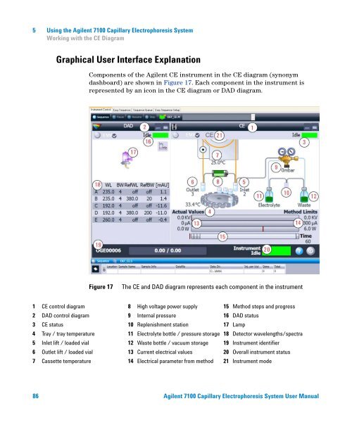
- Page 85: Using the Agilent 7100 Capillary El
- Page 89 and 90: Using the Agilent 7100 Capillary El
- Page 91 and 92: Using the Agilent 7100 Capillary El
- Page 93 and 94: Using the Agilent 7100 Capillary El
- Page 95 and 96: Using the Agilent 7100 Capillary El
- Page 97 and 98: Using the Agilent 7100 Capillary El
- Page 99 and 100: Using the Agilent 7100 Capillary El
- Page 101 and 102: Using the Agilent 7100 Capillary El
- Page 103 and 104: Using the Agilent 7100 Capillary El
- Page 105 and 106: Using the Agilent 7100 Capillary El
- Page 107 and 108: Using the Agilent 7100 Capillary El
- Page 109 and 110: Using the Agilent 7100 Capillary El
- Page 111 and 112: Using the Agilent 7100 Capillary El
- Page 113 and 114: Using the Agilent 7100 Capillary El
- Page 115 and 116: Using the Agilent 7100 Capillary El
- Page 117 and 118: Using the Agilent 7100 Capillary El
- Page 119 and 120: Using the Agilent 7100 Capillary El
- Page 121 and 122: Using the Agilent 7100 Capillary El
- Page 123 and 124: Using the Agilent 7100 Capillary El
- Page 125 and 126: Using the Agilent 7100 Capillary El
- Page 127 and 128: Using the Agilent 7100 Capillary El
- Page 129 and 130: Using the Agilent 7100 Capillary El
- Page 131 and 132: Using the Agilent 7100 Capillary El
- Page 133 and 134: Using the Agilent 7100 Capillary El
- Page 135 and 136: Using the Agilent 7100 Capillary El
- Page 137 and 138:
Using the Agilent 7100 Capillary El
- Page 139 and 140:
Using the Agilent 7100 Capillary El
- Page 141 and 142:
Using the Agilent 7100 Capillary El
- Page 143 and 144:
Using the Agilent 7100 Capillary El
- Page 145 and 146:
Using the Agilent 7100 Capillary El
- Page 147 and 148:
Using the Agilent 7100 Capillary El
- Page 149 and 150:
Using the Agilent 7100 Capillary El
- Page 151 and 152:
Using the Agilent 7100 Capillary El
- Page 153 and 154:
Using the Agilent 7100 Capillary El
- Page 155 and 156:
Using the Agilent 7100 Capillary El
- Page 157 and 158:
Using the Agilent 7100 Capillary El
- Page 159 and 160:
Using the Agilent 7100 Capillary El
- Page 161 and 162:
Agilent 7100 Capillary Electrophore
- Page 163 and 164:
Troubleshooting and Diagnostics 6 C
- Page 165 and 166:
Troubleshooting and Diagnostics 6 C
- Page 167 and 168:
Troubleshooting and Diagnostics 6 C
- Page 169 and 170:
Troubleshooting and Diagnostics 6 A
- Page 171 and 172:
Agilent 7100 Capillary Electrophore
- Page 173 and 174:
Hardware Information 7 7100 Capilla
- Page 175 and 176:
Hardware Information 7 7100 Capilla
- Page 177 and 178:
Hardware Information 7 Firmware Fir
- Page 179 and 180:
Hardware Information 7 Diode Array
- Page 181 and 182:
Hardware Information 7 Diode Array
- Page 183 and 184:
Hardware Information 7 Installing D
- Page 185 and 186:
Hardware Information 7 External Wat
- Page 187 and 188:
Hardware Information 7 Analog to Di
- Page 189 and 190:
Agilent 7100 Capillary Electrophore
- Page 191 and 192:
Maintenance 8 Overview of Maintenan
- Page 193 and 194:
Maintenance 8 Overview of Maintenan
- Page 195 and 196:
Maintenance 8 Early Maintenance Fee
- Page 197 and 198:
Maintenance 8 Cleaning the Electrod
- Page 199 and 200:
Maintenance 8 Cleaning the Electrod
- Page 201 and 202:
Maintenance 8 Cleaning the Electrod
- Page 203 and 204:
Maintenance 8 Cleaning the Electrod
- Page 205 and 206:
Maintenance 8 Cleaning the Electrod
- Page 207 and 208:
Maintenance 8 Cleaning the Electrod
- Page 209 and 210:
Maintenance 8 Cleaning the Electrod
- Page 211 and 212:
Maintenance 8 Cleaning the Electrod
- Page 213 and 214:
Maintenance 8 Cleaning the Electrod
- Page 215 and 216:
Maintenance 8 Cleaning the Electrod
- Page 217 and 218:
Maintenance 8 Maintenance of the Re
- Page 219 and 220:
Maintenance 8 Maintenance of the Re
- Page 221 and 222:
Maintenance 8 Maintenance of the Re
- Page 223 and 224:
Maintenance 8 Changing the Air Inle
- Page 225 and 226:
Maintenance 8 Changing the Lamp Rem
- Page 227 and 228:
Maintenance 8 Changing the Lamp Ins
- Page 229 and 230:
Agilent 7100 Capillary Electrophore
- Page 231 and 232:
Agilent 7100 Capillary Electrophore
- Page 233 and 234:
Appendix 10 General Safety Informat
- Page 235 and 236:
Appendix 10 Allgemeine Sicherheitsi
- Page 237 and 238:
Appendix 10 Allgemeine Sicherheitsi
- Page 239 and 240:
Appendix 10 Informations générale
- Page 241 and 242:
Appendix 10 Informazioni generali s
- Page 243 and 244:
Appendix 10 Informazioni generali s
- Page 245 and 246:
Appendix 10 Información de segurid
- Page 247 and 248:
Appendix 10 安 全 に 関 する
- Page 249 and 250:
Appendix 10 安 全 に 関 する
- Page 251 and 252:
Appendix 10 一 般 安 全 信 息
- Page 253 and 254:
Appendix 10 Setting Up a Test Sampl
- Page 255 and 256:
Appendix 10 Setting Up a Test Sampl
- Page 257 and 258:
Appendix 10 The Waste Electrical an
- Page 259 and 260:
Appendix 10 Sound Emission Sound Em
- Page 261 and 262:
Appendix 10 Agilent Technologies on
- Page 263 and 264:
Index A accessing 199 accessories 5
- Page 266:
www.agilent.com In This Book This m