- Page 1 and 2: Standard for Fire Safety in Rapid T
- Page 3 and 4: 2.3.13 Restriction of Spread of fla
- Page 5 and 6: SECTION 3.2 - OCC and RTS Facility
- Page 7 and 8: 1.1.4 ABBREVIATIONS The abbreviatio
- Page 9 and 10: 2.1.2.5 Area of Refuge (a) In the s
- Page 11 and 12: 2.1.2.16 A space enclosed by elemen
- Page 13 and 14: 2.1.2.27 A means of egress from the
- Page 15 and 16: 2.1.2.45 The height of station or (
- Page 17 and 18: 2.1.2.64 An enclosed space that is
- Page 19 and 20: 2.1.3 STATION OCCUPANCY 2.1.3.1 The
- Page 21 and 22: CODE Table 2.1.3 APPROVED TRADES AN
- Page 23 and 24: SECTION 2.2 STATION MEANS OF ESCAPE
- Page 25 and 26: 2.2.3 MEANS OF ESCAPE FROM PLATFORM
- Page 27 and 28: 2.2.3.9 Gate-type emergency exits s
- Page 29 and 30: 2.2.4.7 The maximum travel distance
- Page 31 and 32: (iii) Permanently fixed ventilation
- Page 33 and 34: (h) 850mm for doors and gates, and
- Page 35 and 36: 300 mm (iii) The sign shall be loca
- Page 37 and 38: (d) Exit ramps shall be straight wi
- Page 39 and 40: (d) Ventilation 2.2.5.12 ESCALATORS
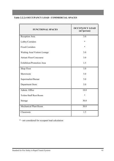
- Page 41 and 42: (ii) All exit access doors which op
- Page 43 and 44: 2.2.5.14 FARE COLLECTION GATES AND
- Page 45: 2.2.5.19 Photo luminescent marking
- Page 49 and 50: Diagram 2.2.5.13(e) - Exit doors sh
- Page 51 and 52: Diagram 2.2.5.16(a)(v) - Remoteness
- Page 53 and 54: SECTION 2.3 STATION STRUCTURAL FIRE
- Page 55 and 56: 2.3.1 GENERAL SECTION 2.3 STATION S
- Page 57 and 58: (c) Commercial spaces shall be comp
- Page 59 and 60: (h) Coldroom Where the enclosure to
- Page 61 and 62: (b) Any reference to height means t
- Page 63 and 64: 2.3.5 EXTERNAL WALL 2.3.5.1 Externa
- Page 65 and 66: 2.3.6.2 A separating wall shall hav
- Page 67 and 68: (b) Have the appropriate fire resis
- Page 69 and 70: 2.3.8.8 A protected shaft which con
- Page 71 and 72: (ii) Drywall shall have the requisi
- Page 73 and 74: 2.3.9.3 Pipes (a) Pipes which pass
- Page 75 and 76: 2.3.10.3 Doors opening into the exi
- Page 77 and 78: (h) All sides shall be properly sea
- Page 79 and 80: (v) Intumescent mastics. The method
- Page 81 and 82: (e) Cl.2.3.8.2(c), 2.3.8.4, 2.3.8.7
- Page 83 and 84: Table 2.3.2A SIZE LIMITATION OF STA
- Page 85 and 86: Table 2.3.9A MAXIMUM NOMINAL INTERN
- Page 87 and 88: Diagram 2.3.3.1(c) - Fire resistanc
- Page 89 and 90: 2.4.1 GENERAL SECTION 2.4 SITE PLAN
- Page 91 and 92: ii) For stations not exceeding the
- Page 93 and 94: 2.4.4 PRIVATE FIRE HYDRANT 2.4.4.1
- Page 95 and 96: (c) Where there are more than one p
- Page 97 and 98:
Diagram 2.4.2.4(b)(vi) U-Turn Radii
- Page 99 and 100:
Diagram 2.4.4.1(b) - Provision of P
- Page 101 and 102:
S2.5.3 Fire protection systems to c
- Page 103 and 104:
2.5.2.5 Portable fire extinguishers
- Page 105 and 106:
2.5.3.5 The dry mains’ breeching
- Page 107 and 108:
2.5.5.2 The fire alarm system shall
- Page 109 and 110:
2.5.6 SPRINKLER INSTALLATION 2.5.6.
- Page 111 and 112:
2.5.7 LIFTS 2.5.7.1 Lifts (includin
- Page 113 and 114:
SECTION 2.6 STATION SMOKE CONTROL A
- Page 115 and 116:
2.6.1 GENERAL SECTION 2.6 STATION S
- Page 117 and 118:
(e) Where the supply air duct servi
- Page 119 and 120:
(c) The smoke purging system design
- Page 121 and 122:
2.6.5.2 The design shall encompass
- Page 123 and 124:
Diagram 2.6.1.4(a) - Fresh/exhaust
- Page 125 and 126:
S2.7.2 Provisions for adequate and
- Page 127 and 128:
(b) Notwithstanding the requirement
- Page 129 and 130:
(g) Exit signs in metal enclosures
- Page 131 and 132:
2.7.2.10 PA systems for stations wi
- Page 133 and 134:
(c) Supply air shall be drawn direc
- Page 135 and 136:
2.8.1 GENERAL SECTION 2.8 INTEGRATI
- Page 137 and 138:
2.8.4.2 Where a station has an unde
- Page 139 and 140:
SECTION 2.9 UNDERGROUND OR ENCLOSED
- Page 141 and 142:
S2.9.10 Provisions for ventilation
- Page 143 and 144:
2.9.2.3 Where underground or enclos
- Page 145 and 146:
2.9.3.5 The emergency lighting shal
- Page 147 and 148:
2.9.6.3 An engineering analysis is
- Page 149 and 150:
2.9.8 MOTORISED TROLLEY 2.9.8.1 Mot
- Page 151 and 152:
Diagram 2.9.4.2 - Numbering and lab
- Page 153 and 154:
ROOT OBJECTIVES SECTION 2.10 ABOVEG
- Page 155 and 156:
2.10.3 EMERGENCY ACCESS 2.10.3.1 Em
- Page 157 and 158:
PART III - RTS DEPOT AND RELATED FA
- Page 159 and 160:
(g) The maximum travel distance for
- Page 161 and 162:
Diagram 3.1.1(d) - Element of Struc
- Page 163 and 164:
For RTS Facility Buildings S3.2.5 P
- Page 165 and 166:
PART IV - ELECTRICAL SYSTEM FOR RAP
- Page 167 and 168:
4.1.3.2 Not withstanding the above,
- Page 169 and 170:
APPENDIX A OCCUPANT LOAD CALCULATIO
- Page 171 and 172:
A.2.3 For a single service centre p
- Page 173 and 174:
A.3.3 For a multi-service centre pl
- Page 175 and 176:
1 2 3 4 5 APPENDIX A, TABLE A : SIN
- Page 177 and 178:
1 2 3 4 5 6 7 8 9 10 11 12 13 14 15
- Page 179 and 180:
1 2 3 4 5 6 7 8 9 10 11 12 13 14 15
- Page 181 and 182:
1 2 3 4 5 6 7 8 9 10 11 12 13 14 15
- Page 183 and 184:
Number of People APPENDIX A, FIGURE
- Page 185 and 186:
B.1 GENERAL APPENDIX B EXITING ANAL
- Page 187 and 188:
any enclosing structure for Escape
- Page 189 and 190:
TEST #2 FOR ESCAPE ROUTE 2 TOTAL WA
- Page 191 and 192:
A. Masonry construction - continued
- Page 193 and 194:
APPENDIX C - continued PART II : RE
- Page 195 and 196:
1. Dense concrete: APPENDIX C - con
- Page 197 and 198:
APPENDIX C - continued PART V : STR
- Page 199 and 200:
APPENDIX C - continued PART VIII :
- Page 201 and 202:
Width of enclosing rectangle in met
- Page 203 and 204:
Width of enclosing rectangle in met
- Page 205 and 206:
Width of enclosing rectangle in met
- Page 207 and 208:
Width of enclosing rectangle in met
- Page 209 and 210:
Width of enclosing rectangle in met
- Page 211 and 212:
APPENDIX E ACCESSWAY E.1 In general
- Page 213 and 214:
APPENDIX F STANDBY FIRE HOSE FOR RI
- Page 215 and 216:
G.1 General APPENDIX G TENABLE ENVI
- Page 217 and 218:
where: tIconv = time in minutes T =
- Page 219 and 220:
APPENDIX H NOTES ON THE USE OF INTU
- Page 221 and 222:
APPENDIX J FIRE SAFETY REQUIREMENTS
- Page 223 and 224:
J.5.3 In the event of fire emergenc