

Download - Academy Publisher
Download - Academy Publisher
Download - Academy Publisher

You also want an ePaper? Increase the reach of your titles
YUMPU automatically turns print PDFs into web optimized ePapers that Google loves.
machining time, machining quality, machining cost<br />
and other especial machining tools or fixtures[6].<br />
Because LMU includes eight elements, and each<br />
element has much different information, through<br />
combining different information of each element, many<br />
LMU-s will be produced and LMU model database will<br />
be set up. Thus, when designing the LMP, designers only<br />
choose the appropriate LMU-s according to the<br />
manufacturing process of a complex part from LMU<br />
model database, in which each LMU has been designed<br />
and defined, so the LMU information of LMP is<br />
relatively static[7]; after choosing the appropriate LMU,<br />
designers should evaluate and compute the machining<br />
time, machining quality, machining cost and point out<br />
the especial machining tools or fixtures for this LMU,<br />
and these information are dynamic, because they are<br />
designed according to this part[8]. The design of LMP is<br />
shown in Fig.1.<br />
part family<br />
geometric<br />
feature<br />
CAD information of<br />
part<br />
CAPP information<br />
of part<br />
LMU(i)<br />
material<br />
type<br />
rough type<br />
Time<br />
requirement<br />
of the LMU<br />
LMU model<br />
database<br />
dimension<br />
range<br />
machining<br />
method<br />
Design LMU<br />
Design LMP<br />
i from 0 to N-1<br />
Cost<br />
requirement<br />
of the LMU<br />
Equipment<br />
demands<br />
Total restriction and weight of time<br />
precision<br />
grade<br />
production<br />
type<br />
Manufacturing<br />
process knowledge<br />
database<br />
Order form<br />
information of<br />
part<br />
Quality<br />
requirement<br />
of the LMU<br />
Fixture<br />
demands<br />
Tool<br />
demands<br />
complex part, and is the mapping result between PMU<br />
and networked manufacturing sub-tasks (LMU-s). EMP<br />
is corresponding to LMP. It is a sequence of several<br />
PMU-s, and includes the detail manufacturing resources<br />
information of PMU-s. The mapping process is shown in<br />
Fig.2.<br />
The 1 st LMU<br />
dynamic<br />
information<br />
The 1 st PMU<br />
Detail resource<br />
information<br />
The 2 st LMU<br />
dynamic<br />
information<br />
The 2 st PMU<br />
Detail resource<br />
information<br />
LMP<br />
EMP<br />
The n st LMU<br />
dynamic<br />
information<br />
Subtask——Manufaturing unit<br />
The n st PMU<br />
Detail resource<br />
information<br />
Networked<br />
manufacturing<br />
task<br />
Mapping<br />
Networked<br />
manufacturing<br />
resource<br />
Fig.2 The mapping process of logical manufacturing tasks and<br />
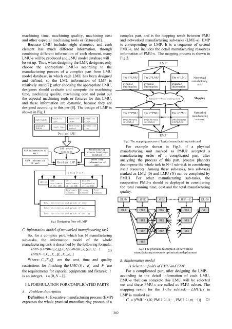
For example shown in Fig.3, if a physical<br />
manufacturing unit marked as PMU1 accepted a<br />
manufacturing order of a complicated part, after<br />
analyzing the process of this part, process planners<br />
decompose the whole task to N+1 sub-task in considering<br />
itself resources. Among these sub-tasks, two sub-tasks<br />
marked as LMU (0) and LMU (N) can be completed by<br />
PMU1. For other manufacturing sub-tasks, the<br />
cooperative PMU-s should be deployed in considering<br />
the total running time, cost and the total manufacturing<br />
quality.<br />
LMU(0) LMU(1) LMU(2) LMU(N-1) LMU(N)<br />
Total restriction and weight of cost<br />
Total restriction and weight of quality<br />
PMU1<br />
PMU3<br />
PMU2<br />
PMU3<br />
PMU1<br />
Fig.1 Designing flow of LMP<br />
PMU4<br />
PMU4<br />
PMU4<br />
C. Information model of networked manufacturing task<br />
So, for a complex part, which has N manufacturing<br />
sub-tasks, the information model of the whole<br />
manufacturing task is described by the following formula:<br />
LMP=<br />
{ LMU(0),<br />
C , T , Q , F,<br />
E ; LMU(1),<br />
C,<br />
T,<br />
Q,<br />
F,<br />
E;<br />
⋅⋅⋅⋅;<br />
0 0 0 0 0<br />
1 1 1 1 1<br />
⑴<br />
LMUN ( −1),<br />
C , T , Q , F , E }<br />
N−1<br />
N−1<br />
N−1<br />
N−1<br />
N−1<br />
Where: C<br />
i, Ti<br />
, Qi<br />
are the cost, time and quality<br />
restrictions for finishing the LMU (i)<br />
; E<br />
i<br />
and F i<br />
are<br />
the requirements for especial equipments and fixtures; i<br />
is an integer, i ∈[ 0, N −1]<br />
.<br />
Ⅲ. FORMULATION FOR COMPLICATED PARTS<br />
A. Problem description<br />
Definition 4: Executive manufacturing process (EMP)<br />
expresses the whole practical manufacturing process of a<br />
PMU5<br />
PMU6<br />
PMU6<br />
PMU5<br />
Fig.3 The problem description of networked<br />
manufacturing resources optimization deployment<br />
B. Mathematics model<br />
1) Selection fields of PMU and EMP<br />
For a complicated part, after designing the LMP,<br />
according to the detail information of each LMU,<br />
PMU-s that can complete this LMU will be selected<br />
out and these PMU-s are called as PMU subset. The<br />
mapping result for the i -the subtask— LMU (i)<br />
in<br />
LMP is marked as:<br />
G { PMU( i,0)<br />
, PMU(<br />
i,1 ),<br />
⋅⋅⋅,<br />
PMU(<br />
i,<br />
m −1 )}<br />
⑵<br />
i<br />
=<br />
i<br />
202


