

Download - Academy Publisher
Download - Academy Publisher
Download - Academy Publisher

Create successful ePaper yourself
Turn your PDF publications into a flip-book with our unique Google optimized e-Paper software.
of DC-driven, and the AC motor with a small size, light<br />
weight, full-enclosed work and so on. Here we focus on<br />
talking about AC spindle drive unit with the spindle axis<br />
associated with the feed control.<br />
1) AC spindle drive unit<br />
This feed AC servo motor using permanent magnet<br />
synchronous motor, but the spindle cage AC motor uses<br />
AC motors, it is because the CNC machine tool numerical<br />
control machine tool spindle drive system without the<br />
feed drive system, as did need such a high dynamic<br />
performance and transfer speed range. We use the vector<br />
control algorithm, the basic idea is through a complex<br />
coordinate transformation to an equivalent AC motor into<br />
a DC motor and controlled. Using this algorithm, AC<br />
motors and DC motors very similar to the mathematical<br />
model, which can be equally good speed performance[4,9].<br />
AC spindle drive unit from the grid-side inverter,<br />
control regulator, the load-side inverter, microprocessor<br />
controller, such as the composition of components.Shown<br />
as Figure 5.<br />
Figure5. AC SPINDLE DRIVE UNIT STRUCTURE<br />
Spindle motor operating characteristics as shown in<br />
Figure 6.<br />
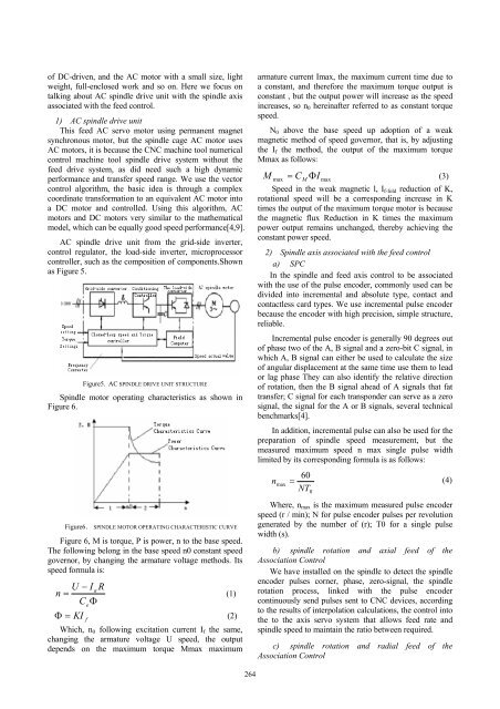
Figure6. SPINDLE MOTOR OPERATING CHARACTERISTIC CURVE<br />
Figure 6, M is torque, P is power, n to the base speed.<br />
The following belong in the base speed n0 constant speed<br />
governor, by changing the armature voltage methods. Its<br />
speed formula is:<br />
U − I<br />
a<br />
R<br />
n =<br />
(1)<br />
CeΦ<br />
Φ = KI<br />
f<br />
(2)<br />
Which, n 0 following excitation current I f the same,<br />
changing the armature voltage U speed, the output<br />
depends on the maximum torque Mmax maximum<br />
armature current Imax, the maximum current time due to<br />
a constant, and therefore the maximum torque output is<br />
constant , but the output power will increase as the speed<br />
increases, so n 0 hereinafter referred to as constant torque<br />
speed.<br />
N 0 above the base speed up adoption of a weak<br />
magnetic method of speed governor, that is, by adjusting<br />
the I f the method, the output of the maximum torque<br />
Mmax as follows:<br />
M<br />
max<br />
CM ΦI max<br />
= (3)<br />
Speed in the weak magnetic l, I f-fold reduction of K,<br />
rotational speed will be a corresponding increase in K<br />
times the output of the maximum torque motor is because<br />
the magnetic flux Reduction in K times the maximum<br />
power output remains unchanged, thereby achieving the<br />
constant power speed.<br />
2) Spindle axis associated with the feed control<br />
a) SPC<br />
In the spindle and feed axis control to be associated<br />
with the use of the pulse encoder, commonly used can be<br />
divided into incremental and absolute type, contact and<br />
contactless card types. We use incremental pulse encoder<br />
because the encoder with high precision, simple structure,<br />
reliable.<br />
Incremental pulse encoder is generally 90 degrees out<br />
of phase two of the A, B signal and a zero-bit C signal, in<br />
which A, B signal can either be used to calculate the size<br />
of angular displacement at the same time use them to lead<br />
or lag phase They can also identify the relative direction<br />
of rotation, then the B signal ahead of A signals that fat<br />
transfer; C signal for each transponder can serve as a zero<br />
signal, the signal for the A or B signals, several technical<br />
benchmarks[4].<br />
In addition, incremental pulse can also be used for the<br />
preparation of spindle speed measurement, but the<br />
measured maximum speed n max single pulse width<br />
limited by its corresponding formula is as follows:<br />
60<br />
n<br />
max<br />
= (4)<br />
NT<br />
0<br />
Where, n max is the maximum measured pulse encoder<br />
speed (r / min); N for pulse encoder pulses per revolution<br />
generated by the number of (r); T0 for a single pulse<br />
width (s).<br />
b) spindle rotation and axial feed of the<br />
Association Control<br />
We have installed on the spindle to detect the spindle<br />
encoder pulses corner, phase, zero-signal, the spindle<br />
rotation process, linked with the pulse encoder<br />
continuously send pulses sent to CNC devices, according<br />
to the results of interpolation calculations, the control into<br />
the to the axis servo system that allows feed rate and<br />
spindle speed to maintain the ratio between required.<br />
c) spindle rotation and radial feed of the<br />
Association Control<br />
264


