

Download - Academy Publisher
Download - Academy Publisher
Download - Academy Publisher

You also want an ePaper? Increase the reach of your titles
YUMPU automatically turns print PDFs into web optimized ePapers that Google loves.
1) Process context storage areas. It is used to store<br />
process contexts before present subsystem is interrupted.<br />
There are two process context storage areas, which are<br />
separately used to store the local subsystem’s contexts<br />
and the network subsystem’s contexts. Certainly, they<br />
have different starting address.<br />
2) Switch back registers. It is used to store address of<br />
the next instruction that present sub-system is going to<br />
execute at the time of being interrupted. There are also<br />
two registers in order to store two sub-systems’ address of<br />
the next instruction separately.<br />
In the next, systemic design of switch mechanism is<br />
elaborated. And then, system-switch flows of booting<br />
and running stages of operating system are illustrated.<br />
III. DESIGN OF SYSTEM-SWITCH MECHANISM<br />
In order to implement the system-switch between two<br />
sub-systems, a system-switch mechanism is designed.<br />
Firstly, as it has two sub-buses and they are both<br />
connected to the shared bus according to the bridge,<br />
some values can be assigned to the bus-bridge controller<br />
register to realize connection with different sub-systems.<br />
Secondly, as mentioned above, process contexts should<br />
be conserved for the sake that sub-systems could run<br />
from the breakpoint. And in our mechanism, clock<br />
interrupt processor is chosen as the breakpoint of<br />
system-switch in order to make system switch in time [5] .<br />
Thirdly, one piece of space in instruction cache is opened<br />
up to conserve the switch-flag. The switch-flag is a<br />
variable which is used to point out whether system need<br />
to be switched or which switch direction should be<br />
adopted. Both of local sub-system and network<br />
sub-system can visit it and change its value. Besides,<br />
switch command is designed so that users can control<br />
system-switch through command. Specific design is<br />
shown as follows:<br />
1) Trigger of system-switch.<br />
System switch mechanism adopts command as the<br />
trigger. Users control systems’ switch through inputting<br />
some commands. After users input switch commands, a<br />
process called switch process will be created. This<br />
process will set the switch flag according to the<br />
parameters of switch command.<br />
2) Entrance of system-switch.<br />
As clock interrupt occurs periodically, it is chosen as<br />
the breakpoint. In our mechanism, clock processor is<br />
modified. Some procedures are added into it which are<br />
used to judge switch flag and then determine whether<br />
system should be switched and which direction should be<br />
changed to.<br />
3) The core switch program.<br />
The core switch program is called bus-switch program,<br />
and it is core module to realize bus switch. Bus-switch<br />
program is located in the instruction cache. And<br />
apparently it has two parts which are used in the different<br />
directions of system switch: local-network bus-switch<br />
program and network-local bus-switch program [6] . They<br />
are stored in different starting addresses of instruction<br />
cache. In this bus-switch program, some functions are<br />
implemented as follows:<br />
a) Store clock interrupt processor’s context of<br />
present sub-system to its process context storage area,<br />
such as the data segment, relevant registers, stack and so<br />
on.<br />
b) Assign specific values to bus bridge controller<br />
register to make shared bus connect to target<br />
sub-system’s bus.<br />
c) Restore the values of target sub-system’s process<br />
context storage area to the relevant registers, stack and so<br />
on. And then, PC register is assigned as the value of<br />
target sub-system’s switch back register.<br />
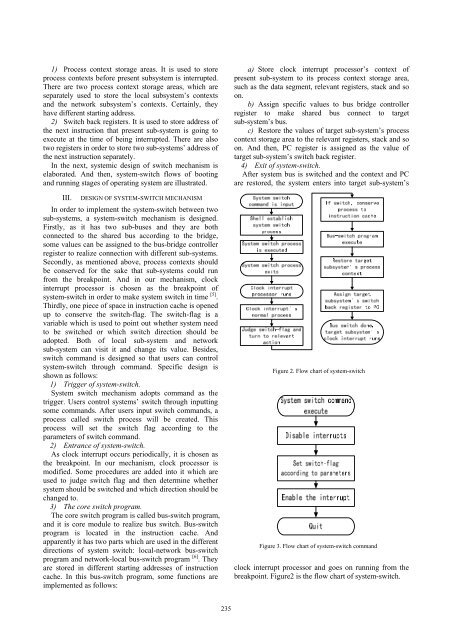
4) Exit of system-switch.<br />
After system bus is switched and the context and PC<br />
are restored, the system enters into target sub-system’s<br />
Figure 2. Flow chart of system-switch<br />
Figure 3. Flow chart of system-switch command<br />
clock interrupt processor and goes on running from the<br />
breakpoint. Figure2 is the flow chart of system-switch.<br />
235


