

Download - Academy Publisher
Download - Academy Publisher
Download - Academy Publisher

Create successful ePaper yourself
Turn your PDF publications into a flip-book with our unique Google optimized e-Paper software.
A. design of system-switch command<br />
When system-switch command is executed, shell will<br />
automatically establish system-switch process. This<br />
process is used to set the switch-flag according to<br />
parameters of system-switch command. Besides, in order<br />
to prevent switch-flag from being changed unexpectedly<br />
when next clock interrupt comes, interrupts should be<br />
disabled during system-switch process is executed. After<br />
switch-flag is set successfully, interrupts will be enabled<br />
again [7] . At last, system-switch process exits. Flow chart<br />
of system-switch command is shown in Figure3.<br />
In order to accomplish the system-switches in<br />
different situations, system-switch command is designed<br />
to have different parameters. And system-switch process<br />
can refer to these parameters to set switch-flag.<br />
System-switch command is called BusSwitch.<br />
Parameters of BusSwitch, its parameters’ meaning and<br />
value of relevant switch flags are shown in table 1.<br />
TABLE 1.<br />
BusSwitch’ parameters and values of relevant switch-flag<br />
BusSwitch –p command values of switch-flag<br />
Parameter’s<br />
Local Network<br />
Meaning of the parameters<br />
value (-p)<br />
subsystem subsystem<br />
Stop system-switch, CPU<br />
n<br />
0 0<br />
works at present sub-area.<br />
u<br />
c<br />
System-switch under users’<br />
control<br />
System-switch during data<br />
transmitting<br />
3 3<br />
1 2<br />
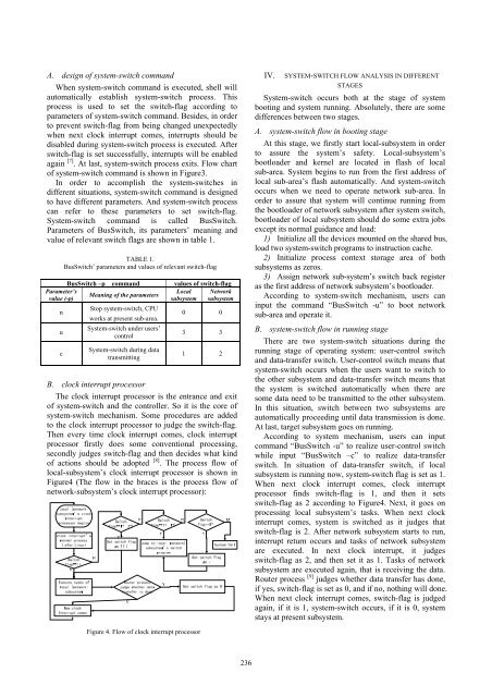
B. clock interrupt processor<br />
The clock interrupt processor is the entrance and exit<br />
of system-switch and the controller. So it is the core of<br />
system-switch mechanism. Some procedures are added<br />
to the clock interrupt processor to judge the switch-flag.<br />
Then every time clock interrupt comes, clock interrupt<br />
processor firstly does some conventional processing,<br />
secondly judges switch-flag and then decides what kind<br />
of actions should be adopted [8] . The process flow of<br />
local-subsystem’s clock interrupt processor is shown in<br />
Figure4 (The flow in the braces is the process flow of<br />
network-subsystem’s clock interrupt processor):<br />
IV.<br />
SYSTEM-SWITCH FLOW ANALYSIS IN DIFFERENT<br />
STAGES<br />
System-switch occurs both at the stage of system<br />
booting and system running. Absolutely, there are some<br />
differences between two stages.<br />
A. system-switch flow in booting stage<br />
At this stage, we firstly start local-subsystem in order<br />
to assure the system’s safety. Local-subsystem’s<br />
bootloader and kernel are located in flash of local<br />
sub-area. System begins to run from the first address of<br />
local sub-area’s flash automatically. And system-switch<br />
occurs when we need to operate network sub-area. In<br />
order to assure that system will continue running from<br />
the bootloader of network subsystem after system switch,<br />
bootloader of local subsystem should do some extra jobs<br />
except its normal guidance and load:<br />
1) Initialize all the devices mounted on the shared bus,<br />
load two system-switch programs to instruction cache.<br />
2) Initialize process context storage area of both<br />
subsystems as zeros.<br />
3) Assign network sub-system’s switch back register<br />
as the first address of network subsystem’s bootloader.<br />
According to system-switch mechanism, users can<br />
input the command “BusSwitch -u” to boot network<br />
sub-area and operate it.<br />
B. system-switch flow in running stage<br />
There are two system-switch situations during the<br />
running stage of operating system: user-control switch<br />
and data-transfer switch. User-control switch means that<br />
system-switch occurs when the users want to switch to<br />
the other subsystem and data-transfer switch means that<br />
the system is switched automatically when there are<br />
some data need to be transmitted to the other subsystem.<br />
In this situation, switch between two subsystems are<br />
automatically proceeding until data transmission is done.<br />
At last, target subsystem goes on running.<br />
According to system mechanism, users can input<br />
command “BusSwitch -u” to realize user-control switch<br />
while input “BusSwitch –c” to realize data-transfer<br />
switch. In situation of data-transfer switch, if local<br />
subsystem is running now, system-switch flag is set as 1.<br />
When next clock interrupt comes, clock interrupt<br />
processor finds switch-flag is 1, and then it sets<br />
switch-flag as 2 according to Figure4. Next, it goes on<br />
processing local subsystem’s tasks. When next clock<br />
interrupt comes, system is switched as it judges that<br />
switch-flag is 2. After network subsystem starts to run,<br />
interrupt return occurs and tasks of network subsystem<br />
are executed. In next clock interrupt, it judges<br />
switch-flag as 2, and then set it as 1. Tasks of network<br />
subsystem are executed again, that is receiving the data.<br />
Router process [9] judges whether data transfer has done,<br />
if yes, switch-flag is set as 0, and if no, nothing will done.<br />
When next clock interrupt comes, switch-flag is judged<br />
again, if it is 1, system-switch occurs, if it is 0, system<br />
stays at present subsystem.<br />
Figure 4. Flow of clock interrupt processor<br />
236


