Handbook of Propagation Effects for Vehicular and ... - Courses
Handbook of Propagation Effects for Vehicular and ... - Courses
Handbook of Propagation Effects for Vehicular and ... - Courses
Create successful ePaper yourself
Turn your PDF publications into a flip-book with our unique Google optimized e-Paper software.
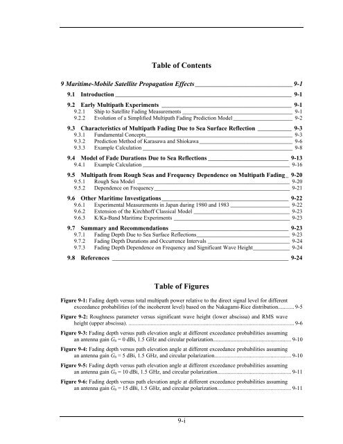
Table <strong>of</strong> Contents<br />
9 Maritime-Mobile Satellite <strong>Propagation</strong> <strong>Effects</strong>_____________________________ 9-1<br />
9.1 Introduction _________________________________________________________ 9-1<br />
9.2 Early Multipath Experiments __________________________________________ 9-1<br />
9.2.1 Ship to Satellite Fading Measurements _______________________________________ 9-1<br />
9.2.2 Evolution <strong>of</strong> a Simplified Multipath Fading Prediction Model _____________________ 9-2<br />
9.3 Characteristics <strong>of</strong> Multipath Fading Due to Sea Surface Reflection ___________ 9-3<br />
9.3.1 Fundamental Concepts____________________________________________________ 9-3<br />
9.3.2 Prediction Method <strong>of</strong> Karasawa <strong>and</strong> Shiokawa_________________________________ 9-6<br />
9.3.3 Example Calculation _____________________________________________________ 9-8<br />
9.4 Model <strong>of</strong> Fade Durations Due to Sea Reflections __________________________ 9-13<br />
9.4.1 Example Calculation ____________________________________________________ 9-16<br />
9.5 Multipath from Rough Seas <strong>and</strong> Frequency Dependence on Multipath Fading_ 9-20<br />
9.5.1 Rough Sea Model ______________________________________________________ 9-20<br />
9.5.2 Dependence on Frequency________________________________________________ 9-21<br />
9.6 Other Maritime Investigations_________________________________________ 9-22<br />
9.6.1 Experimental Measurements in Japan during 1980 <strong>and</strong> 1983 _____________________ 9-22<br />
9.6.2 Extension <strong>of</strong> the Kirchh<strong>of</strong>f Classical Model __________________________________ 9-23<br />
9.6.3 K/Ka-B<strong>and</strong> Maritime Experiments _________________________________________ 9-23<br />
9.7 Summary <strong>and</strong> Recommendations ______________________________________ 9-23<br />
9.7.1 Fading Depth Due to Sea Surface Reflections_________________________________ 9-23<br />
9.7.2 Fading Depth Durations <strong>and</strong> Occurrence Intervals _____________________________ 9-24<br />
9.7.3 Fading Depth Dependence on Frequency <strong>and</strong> Significant Wave Height_____________ 9-24<br />
9.8 References _________________________________________________________ 9-24<br />
Table <strong>of</strong> Figures<br />
Figure 9-1: Fading depth versus total multipath power relative to the direct signal level <strong>for</strong> different<br />
exceedance probabilities (<strong>of</strong> the incoherent level) based on the Nakagami-Rice distribution........... 9-5<br />
Figure 9-2: Roughness parameter versus significant wave height (lower abscissa) <strong>and</strong> RMS wave<br />
height (upper abscissa). ................................................................................................................ 9-6<br />
Figure 9-3: Fading depth versus path elevation angle at different exceedance probabilities assuming<br />
an antenna gain G0 = 0 dBi, 1.5 GHz <strong>and</strong> circular polarization..................................................... 9-10<br />
Figure 9-4: Fading depth versus path elevation angle at different exceedance probabilities assuming<br />
an antenna gain G0 = 5 dBi, 1.5 GHz, <strong>and</strong> circular polarization.................................................... 9-10<br />
Figure 9-5: Fading depth versus path elevation angle at different exceedance probabilities assuming<br />
an antenna gain G0 = 10 dBi, 1.5 GHz, <strong>and</strong> circular polarization.................................................. 9-11<br />
Figure 9-6: Fading depth versus path elevation angle at different exceedance probabilities assuming<br />
an antenna gain G0 = 15 dBi, 1.5 GHz, <strong>and</strong> circular polarization.................................................. 9-11<br />
9-i


