Handbook of Propagation Effects for Vehicular and ... - Courses
Handbook of Propagation Effects for Vehicular and ... - Courses
Handbook of Propagation Effects for Vehicular and ... - Courses
Create successful ePaper yourself
Turn your PDF publications into a flip-book with our unique Google optimized e-Paper software.
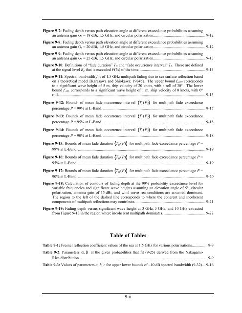
Figure 9-7: Fading depth versus path elevation angle at different exceedance probabilities assuming<br />
an antenna gain G0 = 18 dBi, 1.5 GHz, <strong>and</strong> circular polarization.................................................. 9-12<br />
Figure 9-8: Fading depth versus path elevation angle at different exceedance probabilities assuming<br />
an antenna gain G0 = 20 dBi, 1.5 GHz, <strong>and</strong> circular polarization.................................................. 9-12<br />
Figure 9-9: Fading depth versus path elevation angle at different exceedance probabilities assuming<br />
an antenna gain G0 = 25 dBi, 1.5 GHz, <strong>and</strong> circular polarization.................................................. 9-13<br />
Figure 9-10: Definitions <strong>of</strong> “fade duration” TD <strong>and</strong> “fade occurrence interval” TI. These are defined<br />
at the signal level Rp that is exceeded P(%) <strong>of</strong> the time................................................................ 9-15<br />
Figure 9-11: Spectral b<strong>and</strong>width f-10 <strong>of</strong> 1.5 GHz multipath fading due to sea surface reflection based<br />
on a theoretical model [Karasawa <strong>and</strong> Shiokawa; 1984b]. The upper bound f-10U corresponds<br />
to a significant wave height <strong>of</strong> 5 m, ship velocity <strong>of</strong> 20 knots, with a roll <strong>of</strong> 30°. The lower<br />
bound f-10L corresponds to a significant wave height <strong>of</strong> 1 m, ship velocity <strong>of</strong> 0 knots, with 0°<br />
roll. ............................................................................................................................................ 9-15<br />
Figure 9-12: Bounds <strong>of</strong> mean fade occurrence interval TI (P)<br />
<strong>for</strong> multipath fade exceedance<br />
percentage P = 99% at L-B<strong>and</strong>. .................................................................................................. 9-17<br />
Figure 9-13: Bounds <strong>of</strong> mean fade occurrence interval TI (P)<br />
<strong>for</strong> multipath fade exceedance<br />
percentage P = 95% at L-B<strong>and</strong>. .................................................................................................. 9-18<br />
Figure 9-14: Bounds <strong>of</strong> mean fade occurrence interval TI (P)<br />
<strong>for</strong> multipath fade exceedance<br />
percentage P = 90% at L-B<strong>and</strong>. .................................................................................................. 9-18<br />
Figure 9-15: Bounds <strong>of</strong> mean fade duration TD (P)<br />
<strong>for</strong> multipath fade exceedance percentage P =<br />
99% at L-B<strong>and</strong>. .......................................................................................................................... 9-19<br />
Figure 9-16: Bounds <strong>of</strong> mean fade duration TD (P)<br />
<strong>for</strong> multipath fade exceedance percentage P =<br />
95% at L-B<strong>and</strong>. .......................................................................................................................... 9-19<br />
Figure 9-17: Bounds <strong>of</strong> mean fade duration TD (P)<br />
<strong>for</strong> multipath fade exceedance percentage P =<br />
90% at L-B<strong>and</strong>. .......................................................................................................................... 9-20<br />
Figure 9-18: Calculation <strong>of</strong> contours <strong>of</strong> fading depth at the 99% probability exceedance level <strong>for</strong><br />
variable frequencies <strong>and</strong> significant wave heights assuming an elevation angle <strong>of</strong> 5°, circular<br />
polarization, antenna gain <strong>of</strong> 15 dBi, <strong>and</strong> wind-wave sea conditions are assumed dominant.<br />
The region to the left <strong>of</strong> the dashed line corresponds to where the coherent <strong>and</strong> incoherent<br />
components <strong>of</strong> multipath reflections may contribute.................................................................... 9-21<br />
Figure 9-19: Fading depth versus significant wave height at 3 GHz, 5 GHz, <strong>and</strong> 10 GHz extracted<br />
from Figure 9-18 in the region where incoherent multipath dominates......................................... 9-22<br />
Table <strong>of</strong> Tables<br />
Table 9-1: Fresnel reflection coefficient values <strong>of</strong> the sea at 1.5 GHz <strong>for</strong> various polarizations............... 9-9<br />
Table 9-2: Parameters α, β at the given probabilities that fit (9-25) derived from the Nakagami-<br />
Rice distribution........................................................................................................................... 9-9<br />
Table 9-3: Values <strong>of</strong> parameters a, b, c <strong>for</strong> upper lower bounds <strong>of</strong> –10 dB spectral b<strong>and</strong>width (9-32)... 9-16<br />
9-ii


