- Page 1:
A2A-98-U-0-021 (APL) EERL-98-12A (E
- Page 5 and 6:
Table of Contents 1 Introduction __
- Page 7:
10 Optical Methods for Assessing Fa
- Page 11:
Table of Contents 1 Introduction __
- Page 14 and 15:
1-2 Propagation Effects for Vehicul
- Page 16 and 17:
1-4 Propagation Effects for Vehicul
- Page 18 and 19:
1-6 Propagation Effects for Vehicul
- Page 21 and 22:
Table of Contents 2 Attenuation Due
- Page 23 and 24: Chapter 2 Attenuation Due to Trees:
- Page 25 and 26: Attenuation Due to Trees: Static Ca
- Page 27 and 28: Attenuation Due to Trees: Static Ca
- Page 29 and 30: Attenuation Due to Trees: Static Ca
- Page 31 and 32: Attenuation Due to Trees: Static Ca
- Page 33 and 34: Attenuation Due to Trees: Static Ca
- Page 35 and 36: Attenuation Due to Trees: Static Ca
- Page 37 and 38: Attenuation Due to Trees: Static Ca
- Page 39: Attenuation Due to Trees: Static Ca
- Page 43 and 44: Table of Contents 3 Attenuation Due
- Page 45: Figure 3-23: Fade distributions at
- Page 48 and 49: 3-2 Propagation Effects for Vehicul
- Page 50 and 51: 3-4 Relative Signal Level (dB) 5 0
- Page 52 and 53: 3-6 Propagation Effects for Vehicul
- Page 54 and 55: 3-8 Propagation Effects for Vehicul
- Page 56 and 57: 3-10 Percent of Distance the Fade >
- Page 58 and 59: 3-12 Propagation Effects for Vehicu
- Page 60 and 61: 3-14 3.4.3 Austin, Texas at K-Band
- Page 62 and 63: 3-16 Propagation Effects for Vehicu
- Page 64 and 65: 3-18 Propagation Effects for Vehicu
- Page 66 and 67: 3-20 Relative Signal Level (dB) 5 0
- Page 68 and 69: 3-22 Propagation Effects for Vehicu
- Page 70 and 71: 3-24 Percentage of Distance Fade >
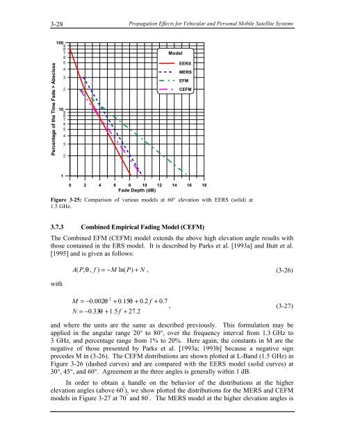
- Page 72 and 73: 3-26 and where 1 2 Propagation Effe
- Page 76 and 77: 3-30 Propagation Effects for Vehicu
- Page 78 and 79: 3-32 3.7.5 Comparative Summary of M
- Page 80 and 81: 3-34 Propagation Effects for Vehicu
- Page 83: Chapter 4 Signal Degradation for Li
- Page 86 and 87: Table of Tables Table 4-1: Summary
- Page 88 and 89: 4-2 Propagation Effects for Vehicul
- Page 90 and 91: 4-4 Percentage of Distance Fade > A
- Page 92 and 93: 4-6 Propagation Effects for Vehicul
- Page 94 and 95: 4-8 Percentage of Distance Fade > A
- Page 96 and 97: 4-10 Propagation Effects for Vehicu
- Page 98 and 99: 4-12 Propagation Effects for Vehicu
- Page 100 and 101: 4-14 Percentage of Distance or Time
- Page 102 and 103: 4-16 Propagation Effects for Vehicu
- Page 105 and 106: Table of Contents 5 Fade and Non-Fa
- Page 107 and 108: Chapter 5 Fade and Non-Fade Duratio
- Page 109 and 110: Fade and Non-Fade Durations and Pha
- Page 111 and 112: Fade and Non-Fade Durations and Pha
- Page 113 and 114: Fade and Non-Fade Durations and Pha
- Page 115 and 116: Fade and Non-Fade Durations and Pha
- Page 117 and 118: Fade and Non-Fade Durations and Pha
- Page 119 and 120: Fade and Non-Fade Durations and Pha
- Page 121: Fade and Non-Fade Durations and Pha
- Page 125 and 126:
Table of Contents 6 Polarization, A
- Page 127 and 128:
Chapter 6 Polarization, Antenna Gai
- Page 129 and 130:
Polarization, Antenna Gain and Dive
- Page 131 and 132:
Polarization, Antenna Gain and Dive
- Page 133 and 134:
Polarization, Antenna Gain and Dive
- Page 135 and 136:
Polarization, Antenna Gain and Dive
- Page 137 and 138:
Polarization, Antenna Gain and Dive
- Page 139 and 140:
Polarization, Antenna Gain and Dive
- Page 141 and 142:
Polarization, Antenna Gain and Dive
- Page 143:
Polarization, Antenna Gain and Dive
- Page 147 and 148:
Table of Contents 7 Investigations
- Page 149:
was derived from measurements over
- Page 152 and 153:
7-2 Propagation Effects for Vehicul
- Page 154 and 155:
7-4 Percentage of Distance Fade > A
- Page 156 and 157:
7-6 7.3 Belgium (PROSAT Experiment)
- Page 158 and 159:
7-8 Percentage of Distance Fade > A
- Page 160 and 161:
7-10 Probability Fade > Abscissa (%
- Page 162 and 163:
7-12 Percentage of Distance Fade >
- Page 164 and 165:
7-14 Percentage of Time Fade > Absc
- Page 166 and 167:
7-16 Percentage of Distance Fade >
- Page 168 and 169:
7-18 Percentage of Distance Fade >
- Page 170 and 171:
7-20 Percentage of Distance Fade >
- Page 172 and 173:
7-22 Percentage of Distance Fade >
- Page 174 and 175:
7-24 Probability (%) > Abscissa 100
- Page 176 and 177:
7-26 Percentage of Distance Fade >
- Page 178 and 179:
7-28 Propagation Effects for Vehicu
- Page 181:
Chapter 8 Earth-Satellite Propagati
- Page 184 and 185:
Table of Figures Figure 8-1: Maximu
- Page 187 and 188:
Chapter 8 Earth-Satellite Propagati
- Page 189 and 190:
Earth-Satellite Propagation Effects
- Page 191 and 192:
Earth-Satellite Propagation Effects
- Page 193 and 194:
Earth-Satellite Propagation Effects
- Page 195 and 196:
Earth-Satellite Propagation Effects
- Page 197 and 198:
Earth-Satellite Propagation Effects
- Page 199 and 200:
Earth-Satellite Propagation Effects
- Page 201 and 202:
Earth-Satellite Propagation Effects
- Page 203 and 204:
Earth-Satellite Propagation Effects
- Page 205 and 206:
Earth-Satellite Propagation Effects
- Page 207 and 208:
Earth-Satellite Propagation Effects
- Page 209 and 210:
Earth-Satellite Propagation Effects
- Page 211 and 212:
Earth-Satellite Propagation Effects
- Page 213 and 214:
Earth-Satellite Propagation Effects
- Page 215 and 216:
Earth-Satellite Propagation Effects
- Page 217 and 218:
Earth-Satellite Propagation Effects
- Page 219 and 220:
Earth-Satellite Propagation Effects
- Page 221 and 222:
Earth-Satellite Propagation Effects
- Page 223:
Chapter 9 Maritime-Mobile Satellite
- Page 226 and 227:
Figure 9-7: Fading depth versus pat
- Page 228 and 229:
9-2 Propagation Effects for Vehicul
- Page 230 and 231:
9-4 Propagation Effects for Vehicul
- Page 232 and 233:
9-6 Roughness Parameter, u (Rad) 28
- Page 234 and 235:
9-8 Cθ = ( θo − 7) / 2 dB for
- Page 236 and 237:
9-10 Fading Depth (dB) 6 5 4 3 2 1
- Page 238 and 239:
9-12 Fading Depth (dB) 6 5 4 3 2 1
- Page 240 and 241:
9-14 Propagation Effects for Vehicu
- Page 242 and 243:
9-16 Propagation Effects for Vehicu
- Page 244 and 245:
9-18 Mean Fade Occurrence Interval,
- Page 246 and 247:
9-20 Mean Fade Duration, T D (sec)
- Page 248 and 249:
9-22 Fade Depth (dB) 7.0 6.5 6.0 5.
- Page 250 and 251:
9-24 Propagation Effects for Vehicu
- Page 252 and 253:
9-26 Propagation Effects for Vehicu
- Page 255 and 256:
Table of Contents 10 Optical Method
- Page 257 and 258:
Chapter 10 Optical Methods for Asse
- Page 259 and 260:
Optical Methods for Assessing Fade
- Page 261 and 262:
Optical Methods for Assessing Fade
- Page 263 and 264:
Optical Methods for Assessing Fade
- Page 265 and 266:
Optical Methods for Assessing Fade
- Page 267 and 268:
Optical Methods for Assessing Fade
- Page 269 and 270:
Optical Methods for Assessing Fade
- Page 271 and 272:
Optical Methods for Assessing Fade
- Page 273 and 274:
Optical Methods for Assessing Fade
- Page 275:
Optical Methods for Assessing Fade
- Page 279 and 280:
Table of Contents 11 Theoretical Mo
- Page 281 and 282:
Chapter 11 Theoretical Modeling Con
- Page 283 and 284:
Theoretical Modeling Considerations
- Page 285 and 286:
Theoretical Modeling Considerations
- Page 287 and 288:
Theoretical Modeling Considerations
- Page 289 and 290:
Theoretical Modeling Considerations
- Page 291 and 292:
Theoretical Modeling Considerations
- Page 293 and 294:
Theoretical Modeling Considerations
- Page 295 and 296:
Theoretical Modeling Considerations
- Page 297 and 298:
Theoretical Modeling Considerations
- Page 299 and 300:
Theoretical Modeling Considerations
- Page 301 and 302:
Theoretical Modeling Considerations
- Page 303 and 304:
Theoretical Modeling Considerations
- Page 305 and 306:
Theoretical Modeling Considerations
- Page 307 and 308:
Theoretical Modeling Considerations
- Page 309 and 310:
Theoretical Modeling Considerations
- Page 311 and 312:
Theoretical Modeling Considerations
- Page 313:
Theoretical Modeling Considerations
- Page 317 and 318:
Table of Contents 12 Summary of Rec
- Page 319:
Table 12-7: Tabulation of azimuth a
- Page 322 and 323:
12-2 Propagation Effects for Vehicu
- Page 324 and 325:
12-4 Propagation Effects for Vehicu
- Page 326 and 327:
12-6 Propagation Effects for Vehicu
- Page 328 and 329:
12-8 Propagation Effects for Vehicu
- Page 330 and 331:
12-10 12.6.5 Satellite Diversity Pr
- Page 332 and 333:
12-12 Propagation Effects for Vehic
- Page 334 and 335:
12-14 Standard Deviation (dB) 4 3 2
- Page 336 and 337:
12-16 Propagation Effects for Vehic
- Page 338 and 339:
12-18 Fade Depth (dB) 7.0 6.5 6.0 5
- Page 340 and 341:
12-20 Propagation Effects for Vehic
- Page 342 and 343:
12-22 Propagation Effects for Vehic
- Page 345 and 346:
Index 13-1 Index 2 2-state Markov m
- Page 347 and 348:
Index 13-3 Jongejans, A. et al., 3-