

How To Rebuild Your Ford V-8 351C-351M-400-429-460.pdf - Index of
How To Rebuild Your Ford V-8 351C-351M-400-429-460.pdf - Index of
How To Rebuild Your Ford V-8 351C-351M-400-429-460.pdf - Index of

Create successful ePaper yourself
Turn your PDF publications into a flip-book with our unique Google optimized e-Paper software.
- -<br />
your<br />
b!<br />
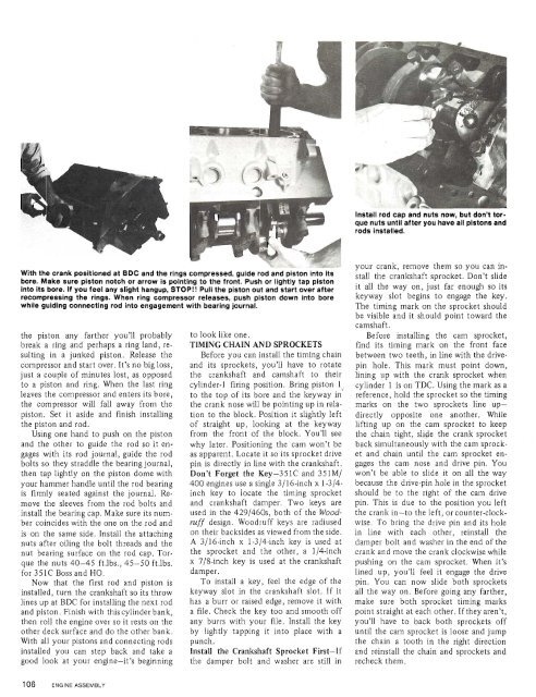
que nuts until after you have all plstons and<br />
rods installed.<br />
crank, remove them so you can in-<br />
With the crank positioned at BDC and the rings compressed, guide rod and piston into Its stall the crankshaft sprocket. D ~ slide ~ * ~<br />
bore. Make sure piston notch or arrow is pointing to the front. Push or lightly tap piston<br />
into its bore. If you feel any slight hangup, STOP!! Pull the piston out and start over after it the way On, just far enough its<br />
recompressing the rings. When ring compressor releases, push piston down into bore keyway slot begins to engage the key.<br />
while guiding connecting rod into engagement with bearing journal.<br />
The timing mark on the sprocket should<br />
be visible and it should point toward the<br />
camshaft.<br />
the piston any farther you'll probably to look like one. Before installing the cam sprocket,<br />
break a ring and perhaps a ring land, re- TIMING CHAIN AND SPROCKETS find its timing mark on the front face<br />
sulting in a junked piston. Release the Before you can install the timing chain between two teeth, in line with the drivecompressor<br />
and start over. It's no big loss, and its sprockets, you'll have to rotate pin hole. This mark must point down,<br />
just a couple <strong>of</strong> minutes lost, as opposed the crankshaft and camshaft to their lining up with the crank sprocket when<br />
to a piston and ring. When the last ring cylinder-1 firing position. Bring piston li cylinder 1 is on TDC. Using the mark as a<br />
leaves the compressor and enters its bore, to the top <strong>of</strong> its bore and the keyway in reference, hold the sprocket so the timing<br />
the compressor will fall away from the the crank nose will be pointing up in rela- , marks on the two sprockets line uppiston.<br />
Set it aside and finish installing tion to the block. Position it slightly left directly opposite one another. While<br />
the piston and rod. <strong>of</strong> straight up, looking at the keyway lifting up on the cam sprocket to keep<br />
Using one hand to push on the piston from the front <strong>of</strong> the block. You'll see the chain tight, slyie the crank sprocket<br />
and the other to guide the rod so it en- why later. Positioning the cam won't be back simultaneously with the cam sprockgages<br />
with its rod journal, guide the rod as apparent. Locate it so its sprocket drive et and chain until the cam sprocket enbolts<br />
so they straddle the bearing journal, pin is directly in line with the crankshaft. gages the cam nose and drive pin. You<br />
then tap lightly on the piston dome with Don't Forget the Key-<strong>351C</strong> and <strong>351M</strong>/ won't be able to slide it on all the way<br />
your hammer handle until the rod bearing <strong>400</strong> engines use a single 3116-inch x 1-314- because the drive-pin hole in the sprocket<br />
is firmly seated against the journal, Re- inch key to locate the timing sprocket should be to the right <strong>of</strong> the cam drive<br />
move the sleeves from the rod bolts and and crankshaft damper. Two keys are pin. This is due to the position you left<br />
install the bearing cap. Make sure its num- used in the <strong>429</strong>/460s, both <strong>of</strong> the Wood- the crank in-to the left, or counter-clockber<br />
coincides with the one on the rod and ruff design. Woodruff keys are radiused wise. <strong>To</strong> bring the drive pin and its hole<br />
is on the same side. Install the attaching on their backsides as viewed from the side, in line with each other, reinstall the<br />
nuts after oiling the bolt threads and the A 3116-inch x 1-314-inch key is used at damper bolt and washer in the end <strong>of</strong> the<br />
nut bearing surface on the rod cap. <strong>To</strong>r- the sprocket and the other, a 114-inch crank and move the crank clockwise while<br />
que the nuts 40-45 ft.lbs., 45-50 ft.lbs. x 718-inch key is used at the crankshaft pushing on the cam sprocket. When it's<br />
for <strong>351C</strong> Boss and HO. damper. lined up, you'll feel it engage the drive<br />
Now that the first rod and piston is <strong>To</strong> install a key, feel the edge <strong>of</strong> the pin. You can now slide both sprockets<br />
installed, turn the crankshaft so its throw keyway slot in the crankshaft slot. If it all the way on. Before going any farther,<br />
lines up at BDC for installing the next rod has a burr or raised edge, remove it with make sure both sprocket timing marks<br />
and piston. Finish with thiscylinder bank, a file. Check the key too and smooth <strong>of</strong>f point straight at each other. Ifthey aren't,<br />
then roll the engine over so it rests on the any burrs with your file. Install the key you'll have to back both sprockets <strong>of</strong>f<br />
other deck surface and do the other bank. by lightly tapping it into place with a until the cam sprocket is loose and jump<br />
With all your pistons and connecting rods punch. the chain a tooth in the right direction<br />
installed you can step back and take a Install the Crankshaft Sprocket First-If and reinstall the chain and sprockets and<br />
good look at your engine-it's beginning the damper bolt and washer are still in recheck them.


