

How To Rebuild Your Ford V-8 351C-351M-400-429-460.pdf - Index of
How To Rebuild Your Ford V-8 351C-351M-400-429-460.pdf - Index of
How To Rebuild Your Ford V-8 351C-351M-400-429-460.pdf - Index of

Create successful ePaper yourself
Turn your PDF publications into a flip-book with our unique Google optimized e-Paper software.
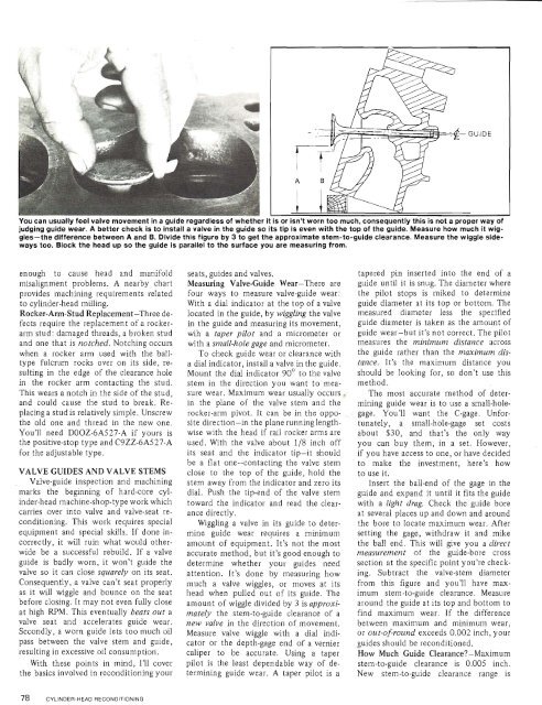
You can usually feel valve movement in a guide regardless <strong>of</strong> whether<br />
judging guide wear. A better check is to install a valve in the guide so its tip is even with the top <strong>of</strong> the guide. Measure how much it wiggles-the<br />
difference between A and B. Divide this figure by 3 to get the approximate stem-to-guide clearance. Measure the wiggle sideways<br />
too. Block the head up so the guide is parallel to the surface you are measuring from.<br />
enough to cause head and manifold<br />
misalignment problems. A nearby chart<br />
provides machining requirements related<br />
to cylinder-head milling.<br />
Rocker-Arm-Stud Replacement-Three defects<br />
require the replacement <strong>of</strong> a rockerarm<br />
stud: damaged threads, a broken stud<br />
and one that isnotched. Notching occurs<br />
when a rocker arm used with the balltype<br />
fulcrum rocks over on its side, resulting<br />
in the edge <strong>of</strong> the clearance hole<br />
in the rocker arm contacting the stud.<br />
This wears a notch in the side <strong>of</strong> the stud,<br />
and could cause the stud to break. Replacing<br />
a stud is relatively simple. Unscrew<br />
the old one and thread in the new one.<br />
You'll need DOOZ-6A527-A if yours is<br />
the positive-stop type and C9ZZ-6A527-A<br />
for the adjustable type.<br />
VALVE GUIDES AND VALVE STEMS<br />
Valve-guide inspection and machining<br />
marks the beginning <strong>of</strong> hard-core cylinder-head<br />
machine-shop-type work which<br />
carries over into valve and valve-seat reconditioning.<br />
This work requires special<br />
equipment and special skills. If done incorrectly,<br />
it will ruin what would otherwide<br />
be a successful rebuild. If a valve<br />
guide is badly worn, it won't guide the<br />
valve so it can close squarely on its seat.<br />
Consequently, a valve can't seat properly<br />
as it will wiggle and bounce on the seat<br />
before closing. It may not even fully close<br />
at high RPM. This eventually beats out a<br />
valve seat and accelerates guide wear.<br />
Secondly, a worn guide lets too much oil<br />
pass between the valve stem and guide,<br />
resulting in excessive oil consumption.<br />
With these points in mind, I'll cover<br />
the basics involved in reconditioning your<br />
seats, guides and valves.<br />
Measuring Valve-Guide Wear-There are<br />
four ways to measure valve-guide wear:<br />
With a dial indicator at the top <strong>of</strong> a valve<br />
located in the guide, by wiggling the valve<br />
in the guide and measuring its movement,<br />
wih a taper pilot and a micrometer or<br />
with a small-hole gage and micrometer.<br />
<strong>To</strong> check guide wear or clearance with<br />
a dial indicator, install a valve in the guide.<br />
Mount the dial indicator 90" to the valve<br />
stem in the direction you want to measure<br />
wear. Maximum wear usually occurs.<br />
in the plane <strong>of</strong> the valve stem and the<br />
rocker-arm pivot. It can be in the opposite<br />
direction-in the plane running lengthwise<br />
with the head if rail rocker arms are<br />
used. With the valve about 118 inch <strong>of</strong>f<br />
its seat and the indicator tip-it should<br />
be a flat one-contacting the valve stem<br />
close to the top <strong>of</strong> the guide, hold the<br />
stem away from the indicator and zero its<br />
dial. Push the tip-end <strong>of</strong> the valve stem<br />
toward the indicator and read the clearance<br />
directly.<br />
Wiggling a valve in its guide to determine<br />
guide wear requires a minimum<br />
amount <strong>of</strong> equipment. It's not the most<br />
accurate method, but it's good enough to<br />
determine whether your guides need<br />
attention. It's done by measuring how<br />
much a valve wiggles, or moves at its<br />
head when pulled out <strong>of</strong> its guide. The<br />
amount <strong>of</strong> wiggle divided by 3 is approximately<br />
the stem-to-guide clearance <strong>of</strong> a<br />
new valve in the direction <strong>of</strong> movement.<br />
Measure valve wiggle with a dial indicator<br />
or the depth-gage end <strong>of</strong> a vernier<br />
caliper to be accurate. Using a taper<br />
pilot is the least dependable way <strong>of</strong> determining<br />
guide wear. A taper pilot is a<br />
tapered pin inserted into the end <strong>of</strong> a<br />
guide until it is snug. The diameter where<br />
the pilot stops is miked to determine<br />
guide diameter at its top or bottom. The<br />
measured diameter less the specified<br />
guide diameter is taken as the amount <strong>of</strong><br />
guide wear-but it's not correct. The pilot<br />
measures the minimum distance across<br />
the guide rather than the maximum distance.<br />
It's the maximum distance you<br />
should be looking for, so don't use this<br />
method.<br />
The most accurate method <strong>of</strong> determining<br />
guide wear is to use a small-holegage.<br />
You'll want the C-gage. Unfortunately,<br />
a small-hole-gage set costs<br />
about $30, and that's the only way<br />
you can buy them, in a set. <strong>How</strong>ever,<br />
if you have access to one, or have decided<br />
to make the investment, here's how<br />
to use it.<br />
Insert the ball-end <strong>of</strong> the gage in the<br />
guide and expand it until it fits the guide<br />
with a light drag. Check the guide bore<br />
at several places up and down and around<br />
the bore to locate maximum wear. After<br />
setting the gage, withdraw it and mike<br />
the ball end. This will give you a direct<br />
measurement <strong>of</strong> the guide-bore cross<br />
section at the specific point you're checking.<br />
Subtract the valve-stem diameter<br />
from this figure and you'll have maximum<br />
stem-to-guide clearance. Measure<br />
around the guide at its top and bottom to<br />
find maximum wear. If the difference<br />
between maximum and minimum wear,<br />
or out-<strong>of</strong>round exceeds 0.002 inch, your<br />
guides should be reconditioned.<br />
<strong>How</strong> Much Guide Clearance-Maximum<br />
stem-to-guide clearance is 0.005 inch.<br />
New stem-to-guide clearance range is


