

How To Rebuild Your Ford V-8 351C-351M-400-429-460.pdf - Index of
How To Rebuild Your Ford V-8 351C-351M-400-429-460.pdf - Index of
How To Rebuild Your Ford V-8 351C-351M-400-429-460.pdf - Index of

You also want an ePaper? Increase the reach of your titles
YUMPU automatically turns print PDFs into web optimized ePapers that Google loves.
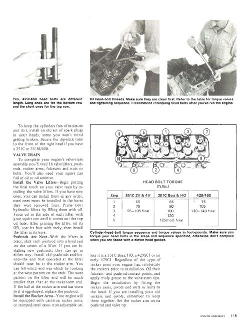
Yes, <strong>429</strong>/460 head bolts are different<br />
length. Long ones are for the bottom row<br />
and the short ones for the top row.<br />
Oil head-bolt threads. Make sure they are clean first. Refer to the table for torque values<br />
and tightening sequence. I recommend retorquing head bolts after you've run the engine.<br />
<strong>To</strong> keep the cylinders free <strong>of</strong> moisture<br />
and dirt, install an old set <strong>of</strong> spark plugs<br />
in your heads, some you won't mind<br />
getting broken. Secure the dip-stick tube.<br />
to the front <strong>of</strong> the right head if you have<br />
a <strong>351C</strong> or <strong>351M</strong>1<strong>400</strong>.<br />
VALVE TRAIN<br />
<strong>To</strong> complete your engine's valve-train<br />
assembly you'!! need 16 valve lifters, pushrods,<br />
rocker arms, fulcrliins and nuts or<br />
bolts. You'll also need your squiri can<br />
full <strong>of</strong> oil or oil additive.<br />
Install the Valve Lifters-Begin putting<br />
the final touch on your valve train by installing<br />
the valve lifters. If you have new<br />
ones, you can install .themlin any order;<br />
used ones must be installed in the bores<br />
they were removed from. Prime your<br />
hydraulic lifters by filling them with oil.<br />
Force oil in the side <strong>of</strong> each lifter with<br />
your squirt can until it comes out the top<br />
oil hole. After priming the lifter, oil its<br />
OD, coat its foot with moly, then install<br />
the lifter in its b0~e.<br />
Pushrods Are Next-With the lifters in<br />
place, slide each pushrod into a head and<br />
on the center <strong>of</strong> a lifter. If you are installing<br />
new pushrods, they can go in<br />
either way. Install old pushrods end-forend-the<br />
end that operated at the lifter<br />
should now be at the rocker arm. You<br />
can tell which end was which by looking<br />
at the wear pattern on the ends. The wear<br />
pattern on the lifter end will be much<br />
smaller than that at the rocker-arm end.<br />
If the ball at the rocker-arm end has worn<br />
so it is egg-shaped, replace the pushrod.<br />
Install the Rocker Arms-<strong>Your</strong> engine will<br />
be equipped with cast-iron rocker arms,<br />
or stamped-steel ones-non-adjustable un-<br />
Step 351 C-2V & 4V 351 C Boss & HO <strong>429</strong>1460<br />
1 65 65 = 75<br />
2 75 80 105<br />
3 95-1 05 final 100 130-140 final<br />
4<br />
5<br />
I<br />
Cylinder-head-bolt torque sequence and torque values in foot-pounds. Make sure you<br />
torque your head bolts in the steps and sequence specified, otherwise don't complain<br />
when you are faced with a blown head gasket.<br />
less it is a 351 C Boss, HO, a <strong>429</strong>SCJ or an<br />
early <strong>429</strong>CJ. Regardless <strong>of</strong> the type <strong>of</strong><br />
rocker arms your engine has, relubricate<br />
the rockers prior to installation. Oil their<br />
fulcrum- and pushrod-contact points, and<br />
apply moly grease to the valve-stem tips.<br />
Begin the installation by fitting the<br />
rocker arms, pivots and nuts or bolts to<br />
the head. If you are installing your old<br />
rockers and pivots, remember to keep<br />
them together. Set the rocker arm on its<br />
pushrod and valve tip.<br />
120<br />
125(hol) final


