

How To Rebuild Your Ford V-8 351C-351M-400-429-460.pdf - Index of
How To Rebuild Your Ford V-8 351C-351M-400-429-460.pdf - Index of
How To Rebuild Your Ford V-8 351C-351M-400-429-460.pdf - Index of

Create successful ePaper yourself
Turn your PDF publications into a flip-book with our unique Google optimized e-Paper software.
used, but good cam and its lifters in an<br />
engine other than the one in which they<br />
were originally installed. The lifter bore<br />
centers will not be in the same exact<br />
relationship to the cam lobes as in its<br />
original engine. So this is similar to<br />
mixing up the lifters.<br />
Almost without exception, the rules<br />
realted to proper cam and lifter combinations<br />
and installation methods have to<br />
do with avoiding excessively high contact<br />
pressure between cam lobes and lifters.<br />
Loads exerted between a cam and its<br />
lifters during normal operating conditions<br />
are extremely high. Consequently,<br />
if there's any wrong move with the choice<br />
<strong>of</strong> cam components and their installation<br />
between now and the first 30 minutes <strong>of</strong><br />
engine operation, the chances <strong>of</strong> a carnshaft<br />
and its lifters being ruined are very<br />
high. It's important to adhere to proper<br />
procedures when choosing and installing<br />
your camshaft.<br />
Camshaft Lobe and Lifter Design-For a<br />
clear understanding <strong>of</strong> why certain things<br />
have to be done when dealing with your<br />
engine's camshaft and lifters, a quick<br />
lesson in cam lobe and lifter design is in<br />
order. First is the pr<strong>of</strong>ile <strong>of</strong> a lobe, or<br />
what one looks like when viewed from<br />
the cam end. A cam's pr<strong>of</strong>ile governs<br />
how far its valves open in addition to<br />
when they open and close. This is an<br />
oversimplification, but it's OK for our<br />
purposes.<br />
When a valve is closed, the lifter is on<br />
the base circle <strong>of</strong> the cam lobe described<br />
by a radius. When the lifter is on the highest<br />
point <strong>of</strong> the lobe, it's on the toe <strong>of</strong><br />
the lobe and the valve is fully open. Be-<br />
tween the base circle and the toe are the<br />
opening and closing ramps. Sketch on<br />
page 63 shows the difference between the<br />
base-circle diameter and the distance<br />
from the toe directly across the camshaft<br />
centerline to the base circle is cam lift at<br />
the lifter-not the valve.<br />
During the camshaft manufacturing<br />
process, lobe surfaces are not ground<br />
parallel to the camshaft centerline, but<br />
are ground at a rake angle-lo in most<br />
instances. Also, the lifter foot that contacts<br />
the cam is not ground flat, but has<br />
a spherical radius, or is ground convex.<br />
<strong>Ford</strong> uses a 30-inch radius. At first this<br />
sounds odd because one would think<br />
pressure between the lobe and lifter<br />
would go up as area between the two is<br />
reduced. <strong>How</strong>ever, this machining ensures<br />
a reasonable and predictable contact<br />
pressure within practical machining tolerances.<br />
The lifter-foot radius and lobe<br />
angle guarantee good cam-to-lifter contact<br />
area for consistent camshaft and<br />
lifter life.<br />
The way camshafts and lifters are<br />
machined serves another important function.<br />
Cam-lobe contact is made <strong>of</strong>f-center<br />
rather than directly on the lobe's center.<br />
Consequently, the lifter rotates to minimize<br />
wear <strong>of</strong> the two components and to<br />
ensure good lifter and bore lubrication.<br />
CAM & LIFTER INSPECTION<br />
During their operating life, a cam and<br />
its lifters wear gradually. <strong>How</strong> much de"-<br />
pends on how an engine is operated and,<br />
more importantly, how it is maintained.<br />
You must determine whether yours has<br />
worn so badly that it shouldn't be used.<br />
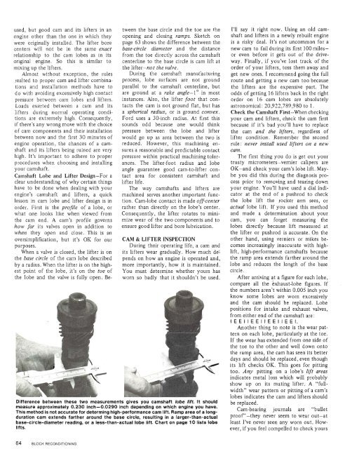
Difference between these two measurements gives you camshaft lobe lift. It should<br />
measure approximately 0.230 inch-0.0290 inch depending on which engine you have.<br />
This method is not accurate for determing high-performance cam lift. Ramp area <strong>of</strong> a longduration<br />
cam extends farther around the base circle, resulting in a larger-than-actual<br />
base-circle-diameter reading, or a less-than-actual lobe lift. Chart on page 10 lists lobe<br />
lifts.<br />
I'll say it right now. Using an old camshaft<br />
and lifters in a newly rebuilt engine<br />
is a risky deal. It's not uncommon for a<br />
new cam to fail during its first 100 milesor<br />
even before it gets out <strong>of</strong> the driveway.<br />
Finally, if you've lost track <strong>of</strong> the<br />
order <strong>of</strong> your lifters, toss them away and<br />
get new ones. I recommend going the full<br />
route and getting a new cam too because<br />
the lifters are the expensive part. The<br />
odds <strong>of</strong> getting 16 lifters back in the right<br />
order on 16 cam lobes are absolutely<br />
astronomical: 20,922,789,980 to 1.<br />
Check the Camshaft First-When checking<br />
your cam and lifters, check the cam first<br />
because if it's bad you'll have to replace<br />
the cam and the lifters, regardless <strong>of</strong><br />
lifter condition. Remember the second<br />
rule: never install used lifters on a new<br />
cam.<br />
The first thing you do is get out your<br />
trusty micrometers-vernier calipers are<br />
OK-and check your cam's lobe lift. Maybe<br />
you did this during the diagnosis process<br />
prior to removing and tearing down<br />
your engine. You'll have used a dial indicator<br />
at the end <strong>of</strong> a pushrod to check<br />
the lobe lift the rocker arm sees, or<br />
actual lobe lift. If you used this method<br />
and made a determination about your<br />
cam, you can forget measuring the<br />
lobes directly because lift measured at<br />
the lifter or pushrod is accurate. On the<br />
other hand, using verniers or mikes becomes<br />
increasingly inaccurate with highlift,<br />
high-performance camshafts because<br />
the ramp area extends farther around the<br />
lobe and reduces the length <strong>of</strong> the base<br />
circle.<br />
After arriving at a figure for each lobe,<br />
compare all the exhaust-lobe figures. If<br />
the numbers aren't within 0.005 inch you<br />
know some lobes are worn excessively<br />
and the cam should be replaced. Lobe<br />
positions for intake and exhaust valves,<br />
from either end <strong>of</strong> the camshaft are:<br />
IEEIIEEIIEEIIEEI.<br />
Another thing to note is the wear pattern<br />
on each lobe, particularly at the toe.<br />
If the wear has extended from one side <strong>of</strong><br />
the toe to the other and well down onto<br />
the ramp area, the cam has seen its better<br />
days and should be replaced, even though<br />
its lift checks OK. This goes for pitting<br />
too. Any pitting on a lobe's lift areas<br />
indicates metal loss which will probably<br />
show up on its mating lifter. A "fullwidth"<br />
wear pattern or pitting <strong>of</strong> a cam's<br />
lobes indicates the cam and lifters should<br />
be replaced.<br />
Cam-bearing journals are "bullet<br />
pro<strong>of</strong> '-they never seem to wear out-at<br />
least I've never seen any worn out. <strong>How</strong>ever,<br />
if you feel compelled to check yours


