

How To Rebuild Your Ford V-8 351C-351M-400-429-460.pdf - Index of
How To Rebuild Your Ford V-8 351C-351M-400-429-460.pdf - Index of
How To Rebuild Your Ford V-8 351C-351M-400-429-460.pdf - Index of

You also want an ePaper? Increase the reach of your titles
YUMPU automatically turns print PDFs into web optimized ePapers that Google loves.
spots, the rod/s need to be checked with<br />
a dial-indicator that's part <strong>of</strong> an engine<br />
builder's connecting-rod conditioning<br />
hone. A telescoping gage and micrometer<br />
can also be used for checking. Recondition<br />
the rod/s as necessary.<br />
When a connecting rod is reconditioned,<br />
some material is precision ground<br />
from the bearing-cap mating surfaces.<br />
Next, the cap is reinstalled on the rod,<br />
bolts are torqued to spec and the bore is<br />
honed to the specified diameter. Honing<br />
corrects the bearing-bore diameter and<br />
concentricity and also restores the tooth,<br />
or surface <strong>of</strong> the bore which grabs the<br />
bearing insert to prevent it from spinning.<br />
Rod Bolts-Make sure you inspect the rod<br />
bolts very closely before attempting any<br />
other reconditioning <strong>of</strong> the rods. Don't<br />
hesitate to use a magnifying glass as you<br />
give them the old "eagle-eye." Replace<br />
any cracked bolts-a cracked rod bolt<br />
will eventually break and may totally<br />
destroy any engine.<br />
You have to remove the bolts to check<br />
them. <strong>To</strong> remove a rod bolt, clamp the<br />
big end <strong>of</strong> the rod in a vise between two<br />
blbcks <strong>of</strong> wood and drive the bolt straight<br />
out. Use something such as a brass punch<br />
to do this to prevent damaging the bolt.<br />
The original or new bolt can be installed<br />
by tightening it after it is loosely installed<br />
in the rod with the cap. If you replace<br />
one or both rod bolts, the connecting rod<br />
must be reconditioned or honed because<br />
the bolts locate the cap in relation to the<br />
rod. Consequently, changing a bolt may<br />
shift the cap in relation to the connecting<br />
rod.<br />
One last note concerning connecting<br />
rods. Rod-bearing bores are originally<br />
machined with their caps torqued in<br />
place, so they must be checked the same<br />
way.-When you deliver them to a machine<br />
shop for checking and reconditioning<br />
after you've inspected the rod bolts,<br />
make sure the correct cap is installed in<br />
each rod. <strong>To</strong>rque the nutsto specification<br />
before making the delivery; 40-45 ft. Ibs.;<br />
45-50 ft. Ibs. for <strong>351C</strong> Boss and HO.<br />
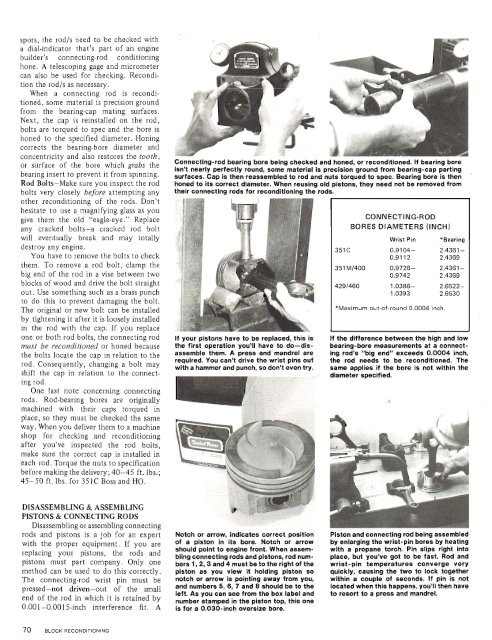
Connecting-rod bearing bore being checked and honed, or reconditioned. Ii - re<br />
isn't nearly perfectly round, some material is precision ground from bearing-cap parting<br />
surfaces. Cap is then reassembled to rod and nuts torqued to spec. Bearing bore is then<br />
honed to its correct dlameter. When reusing old pistons, they need not be removed from<br />
their connectlng rods for reconditlonlng the rods.<br />
CONNECTING-ROD<br />
BORES DIAMETERS (INCH)<br />
Wrist Pin<br />
*Bearing<br />
<strong>351C</strong> 0.9104-<br />
0.9112 2.4361 -<br />
2.4369<br />
351 MI<strong>400</strong> 0.9726-<br />
0.9742<br />
2.4361-<br />
2.4369<br />
<strong>429</strong>1460 1.0386-<br />
1.0393<br />
2.6522-<br />
2.6530<br />
*Maximum out-<strong>of</strong>-round 0.0004 inch.<br />
If your pistons have to be replaced, this is If the difference between the high and low<br />
the first operation you'll have to do-dis- bearing-bore measurements at a connectassemble<br />
them. A press and mandrel are ing rod's "blg end" exceeds 0.0004 inch,<br />
required. You can't drive the wrlst pins ouf the rod needs to be reconditioned. The<br />
with a hammer and punch, so don't even try. same applies if the bore is not within the<br />
-..._,.. - diameter specified.<br />
DISASSEMBLING & ASSEMBLING<br />
PISTONS & CONNECTING RODS<br />
Disassembling or assembling connecting<br />
rods and pistons is a job for an expert<br />
with the proper equipment. If you are<br />
replacing your pistons, the rods and<br />
pistons must part company. Only one<br />
method can be used to do this correctly.<br />
The connecting-rod wrist pin must be<br />
pressed-not driven-out <strong>of</strong> the small<br />
end <strong>of</strong> the rod in which it is retained by<br />
0.001 -0.001 5-inch interference fit. A<br />
Notch or arrow, indicates correct position<br />
<strong>of</strong> a piston in its bore. Notch or arrow<br />
should point to engine front. When assembling<br />
connecting rods and pistons, rod numbers<br />
l,2,3 and 4 must be to the right <strong>of</strong> the<br />
piston as you view It holding piston so<br />
notch or arrow is pointing away from you,<br />
and numbers 5,6, 7 and 8 should be to the<br />
left. As you can see from the box label and<br />
number stamped in the piston top, this one<br />
is for a 0.030-inch oversize bore.<br />
Piston and connecting rod being assembled<br />
by enlarging the wrist-pin bores by heating<br />
with a propane torch. Pln slips right into<br />
place, but you've got to be fast. Rod and<br />
wrist-pln temperatures converge very<br />
quickly, causing the two to lock together<br />
within a couple <strong>of</strong> seconds. If pin is not<br />
located when this happens, you'll then have<br />
to resort to a press and mandrel.


